Ask our team:
  • Phone: +86 181 0690 9650
  • E-Mail sales1@apterpower.com
  • Lifecycle status

    Discontinued / Obsolete by OEM
    Contact Apter Power for DS200DTBAG1A quotation assistance, applicable manufacturer manuals, or help confirming whether an official replacement model has been specified.

DS200DTBAG1A

/ 4.9
1001 reviews | Need a Specific Revision?
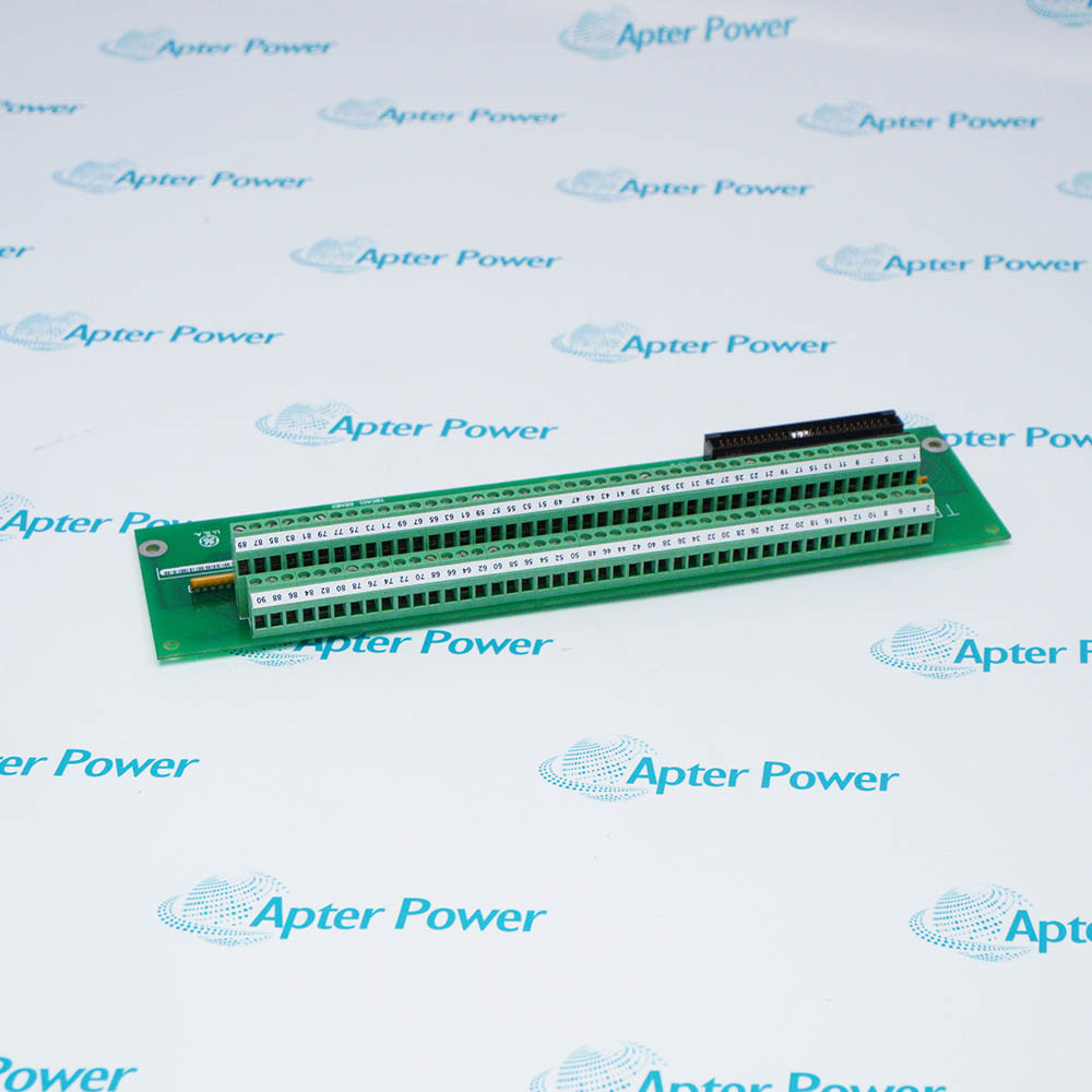
General Electric DS200DTBAG1A is a Mark V LM contact input termination module that connects the first 46 field contact inputs in a digital core to the associated TCDA board.
In Stock
Ships by Thursday, October 29
Fast Shipping Available
Get a quick price for DS200DTBAG1A
Quantity
*E-mail
Company
*Mobile
*Content
Upload (gif, jpg, jpeg, png, bmp, doc, docx, xls, xlsx, ppt, pdf, csv)

Technical specifications for DS200DTBAG1A

  • Manufacturer:
    General Electric
  • Part Number:
    DS200DTBAG1A
  • Product Family:
    GE Mark V/VI Driver Board
  • Product Type:
    Contact Input Termination Module
  • Stock:
    1
  • Control Platform:
    Mark V LM SPEEDTRONIC
  • Core Locations:
    , , and
  • Input Bank:
    First 46 contact inputs
  • Controller Interface:
    JQR to TCDA
  • Contact Power Path:
    J12 from TCPD; JY to DTBB
  • Test Isolation:
    BJ1 through BJ5
  • Sense Configuration:
    Inversion in TCDA I/O Configuration
  • Tariff Code:
    8538900000
  • Country of origin:
    USA
  • Place of shipment:
    Xiamen,Fujian,China
By purchasing this item, you agree to the Terms & Conditions, ApterPower is not an authorized distributor for listed manufacturers or tradenames and therefore the manufacturer's warranty does not apply. All our products come with ApterPower's 1-year warranty.

More Information

Overview Manuals Input Bank Power Feed Test Isolation Input Sense

Features:

  • Terminates the first 46 contact inputs in a Mark V LM digital core.
  • Uses JQR for the TCDA signal path and J12 for 125 V DC contact power.
  • BJ1 through BJ5 isolate defined input groups for testing.
DS200DTBAG1A is installed in the Q11, Q21, and Q51 digital cores. It forms the first contact-input termination bank for the TCDA board in the same core.

JY extends the contact-power feed from DTBA to the companion DTBB expansion bank. JQS and JQT are normally unused.

Failsafe contact behavior is implemented through input-sense inversion in the TCDA I/O Configuration, not by reversing the DTBA field wiring.

Apter Power can assist with purchasing and documentation for the General Electric DS200DTBAG1A Contact Input Termination Module beyond manufacturer End-of-Life (EOL).
General Electric DS200DTBAG1A Contact Input Termination Module Manuals, Datasheets, Links Important Notice: Other accessories, manuals, cables, calibration data, software, etc. are not included with this equipment unless listed in the above stock item description. All prices are shown in USD.

First 46 contact inputs

  • Bank assignment: DS200DTBAG1A terminates the first 46 contact-input points assigned to the TCDA board in its digital core. Keeping this bank distinct from the DTBB expansion bank prevents a channel from being traced through the wrong connector.
  • JQR boundary: JQR is the common connection from DTBA to TCDA. A JQR fault can affect a broad set of inputs, while one field-terminal problem is normally limited to its own point.
  • Channel mapping: The terminal schedule and TCDA assignment should identify the same channel before an input is tested or moved.

J12 and JY distribution

  • Incoming and onward feed: J12 receives 125 V DC contact power from TCPD in the power-distribution core. JY carries that contact-power source onward to the adjacent DTBB expansion termination module.
  • Shared-loss pattern: If both DTBA and DTBB banks are affected, start upstream at the J12 feed. If only the DTBB bank is affected, the JY interconnection becomes the more specific boundary.
  • Inactive paths: JQS and JQT are normally unused and should not be treated as alternate operating paths without a matching configured path.

BJ1 through BJ5

  • Group isolation: The five BJ jumpers isolate contact-input groups from the 125 V DC source for test purposes. Opening a group intentionally removes its interrogation power and makes every point in that group appear inactive.
  • Test record: Before using a BJ jumper, record its original position and identify the channels assigned to that group. Restore and verify the group after the test.
  • Restored-group diagnosis: A contact that remains incorrect with the group restored should be checked at the field device, terminal, conductor, and TCDA indication.

Failsafe input behavior

  • Logic inversion: The TCDA I/O Configuration can invert the sense of DTBA contact inputs. This lets the logic interpretation match the required failsafe convention without changing the physical termination function.
  • Reversed indication: When an input reads opposite to the expected state, compare the TCDA inversion setting with the field contact type before moving wires.
  • End-to-end proof: End-to-end validation should operate the real contact and confirm its state at the DTBA terminal and the assigned controller point.
Description
General Electric DS200DTBAG1A is the DTBA Contact Input Termination Module used in the Mark V LM Q11, Q21, and Q51 digital cores. It connects the first 46 contact inputs in the selected core to the TCDA digital I/O board.

Connector JQR carries the DS200DTBAG1A contact-input bank to TCDA. J12 receives 125 V DC contact power from TCPD in the PD core, and JY passes that source onward to the companion DTBB expansion termination module.

BJ1 through BJ5 on DS200DTBAG1A isolate contact-input groups from the 125 V DC source for testing. JQS and JQT are normally unused in the Mark V LM arrangement.

Input sense for DS200DTBAG1A channels can be inverted in the TCDA I/O Configuration to implement the required failsafe contact behavior. The physical termination map and controller assignment together determine the observed input state.
Alternative Names
DS200-DTBA-G1A DS200 DTBA G1A GE DS200DTBAG1A GE Mark V DS200DTBAG1A DS200DTBA G1A DS2O0DTBAG1A DS200DTBAGIA DS200DTBAG1A-GE
Technical notes
DS200DTBAG1A terminates the first 46 contact inputs; J12 receives 125 V DC from TCPD, JQR connects to TCDA, and JY forwards contact power to DTBB.
Exceptional Service

Our Mission

  • 100% Satisfaction

    We believe expertise is priceless. With over 20 years of experience, and top engineers on staff, we can help you solve or avoid problems that threaten your business.
  • Trust Guaranteed

    Not only do we have a vast inventory, our team makes sure every piece of equipment is in working condition. Your purchases are also backed by our Warranty.
  • Expertise

    Time is money, especially when your equipment is down. We work quickly to get your equipment on its way so you can get it back up and running.

FAQS

The following is a list of questions commonly asked by our customers. Please contact us if you have a question about our process that is not answered below.
Why can the first group of contact inputs disappear together?
DS200DTBAG1A shares the J12 contact-power feed and JQR interface across its input bank. Check the 125 V DC supply and the JQR cable before treating multiple simultaneous losses as separate field-device faults.
Why can DTBB inputs be dead while DS200DTBAG1A inputs still work?
DTBB receives its contact power through the JY path on DS200DTBAG1A. An open JY connection can remove the expansion-bank supply while the first input bank remains available.
What should be checked when one DTBA input does not change state?
Confirm the field contact, landed terminal, conductor continuity, and its assigned TCDA point. A single-point symptom usually does not require disturbing the complete JQR group.
Why can an input appear logically reversed after work on DS200DTBAG1A?
The TCDA I/O Configuration can invert contact sense for failsafe operation. Compare the channel setting with the intended field-contact convention before changing wiring.
How can contact groups be isolated during a test?
BJ1 through BJ5 isolate defined contact-input groups from the 125 V DC source. Record every original jumper position and follow the panel drawing before opening a group.
What causes many inputs to change after reconnecting JQR?
A shifted, reversed, or poorly seated JQR cable can affect many channels at once. Verify connector orientation and compare the full input map before changing individual terminals.
How should a restored DTBA channel be proven?
Operate the actual field contact and confirm the expected state at its terminal and assigned TCDA indication, including any configured sense inversion.

Product Browsing History