Ask our team:
  • Phone: +86 181 0690 9650
  • E-Mail info@apterpower.com
  • Lifecycle status

    Discontinued / Obsolete by OEM
    Apter Power provides quotations, documentation and relay-board matching assistance for General Electric DS200RTBAG2A.

DS200RTBAG2A

/ 4.9
1001 reviews | Need a Specific Revision?
General Electric DS200RTBAG2A is a 24 VDC relay terminal board with ten relay positions for cabinet control and protection circuits.
In Stock
Ships by Tuesday, September 29
Fast Shipping Available
Get a quick price for DS200RTBAG2A
Quantity
*E-mail
Company
*Mobile
*Content
Upload (gif, jpg, jpeg, png, bmp, doc, docx, xls, xlsx, ppt, pdf, csv)

Technical specifications for DS200RTBAG2A

  • Manufacturer:
    General Electric
  • Part Number:
    DS200RTBAG2A
  • Product Family:
    GE Mark V/VI Driver Board
  • Product Type:
    24 VDC Relay Terminal Board
  • Stock:
    1
  • Functional Acronym:
    RTBA
  • Relay Coil Voltage:
    24 VDC
  • Relay Quantity:
    10
  • Pilot Interface:
    RPL, 16-pin
  • Auxiliary Interface:
    OPTPL, 2-pin
  • Relay Status Indication:
    On-board indicators
  • Tariff Code:
    8537101190
  • Country of origin:
    USA
  • Place of shipment:
    Xiamen,Fujian,China
By purchasing this item, you agree to the Terms & Conditions, ApterPower is not an authorized distributor for listed manufacturers or tradenames and therefore the manufacturer's warranty does not apply. All our products come with ApterPower's 1-year warranty.

More Information

Overview Manuals Relay Paths Contact Map Coil Source Board Links

Features:

  • Adds ten 24 VDC relay positions for cabinet control and protection circuits.
  • Routes seven pilot-relay commands from the LAN I/O Terminal Board.
  • Selects internal or externally wired coil sources through configurable jumpers.
Ten relay positions on DS200RTBAG2A are divided by contact capacity. K20-K26 serve two changeover circuits each, whereas K27-K29 provide four, allowing each field load to use a position with the required pole count.

DS200RTBAG2A keeps pilot commands and field switching physically distinct. RPL brings seven instructions from the LTB, while the terminal bank presents the corresponding common, normally open and normally closed points to external circuits.

For K20-K26, DS200RTBAG2A does not impose one coil-power origin. The jumper bank selects either the pilot-side control feed or a customer-supplied 24 VDC source, with OPTPL completing the LTB interface.

The General Electric DS200RTBAG2A 24 VDC Relay Terminal Board may still be available for purchase and support from Apter Power beyond End-Of-Life (EOL) by the manufacturer (OEM).
General Electric DS200RTBAG2A 24 VDC Relay Terminal Board Manuals,Datasheets,Link Important Notice: Other accessories, manuals, cables, calibration data, software, etc. are not included with this equipment unless listed in the above stock item description. All prices are shown in USD.

Command Routing

  • Pilot Inputs: Seven LTB relay commands enter through the RPL connector.
  • Local Selection: Jumpers choose the pilot path or externally supplied coil voltage.
  • Contact Use: Relay outputs feed external control and protection circuits.
  • Field Access: Numbered terminals expose the documented changeover contacts.

Relay Contact Arrangement

  • K20-K26: Seven 24 VDC relays provide two Form C contact sets apiece.
  • K27-K29: Three relay positions provide four Form C contact sets apiece.
  • Terminal States: Separate points identify normally open, common, and normally closed paths.
  • State Lamps: Indicators identify energized relay positions on the board.

24 VDC Source Choice

  • Group Rating: The G2 relay group is arranged for 24 VDC coils.
  • Jumper Bank: JP1 through JP7 set the K20-K26 coil-source route.
  • Internal Route: One position accepts control voltage arriving with the LTB pilot signals.
  • External Route: The alternate position accepts customer-wired coil power at the terminal board.

Connector Functions

  • RPL: The 16-pin link carries RX1 through RX7 pilot commands from the LTB.
  • OPTPL: The two-pin link completes the documented LTB interface.
  • CPH and CPN: Stab connections serve positive and negative pluggable-circuit control power.
  • Terminal Bank: Field wiring remains separated from the plug-in command connections.
Description
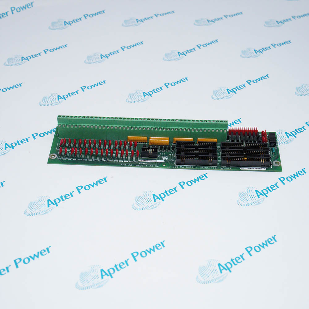
The DS200RTBAG2A is an RTBA Relay Terminal Board for compatible General Electric drive and exciter cabinets. It expands the cabinet interface with ten relay positions and provides field-accessible contacts for external control and protection circuits.

On DS200RTBAG2A, relays K20 through K26 use 24 VDC coils and expose DPDT contact sets, while K27 through K29 provide additional four-pole changeover contacts. Indicator lamps show when individual relays are energized without converting the status display into a separate diagnostic controller.

The DS200RTBAG2A receives seven pilot-relay commands through the 16-pin RPL connection from the LAN I/O Terminal Board. OPTPL supplies the related two-pin interface, and the numbered terminal points separate coil feeds from normally open, common, and normally closed contact paths.

Source-selection jumpers on DS200RTBAG2A allow the K20-K26 coils to follow the LTB pilot path or an externally wired 24 VDC source. CPH and CPN stab connections serve the pluggable-circuit control supply, so the installed jumper pattern and field-voltage route must agree with the cabinet drawing.
Revisions

Revision Part #

Also known as

DS200RTBAG2AFB
DS200RTBAG2A-FB, Series FB, Rev FB
DS200RTBAG2AGC
DS200RTBAG2A-GC, Series GC, Rev GC
Alternative Names
GE DS200RTBAG2A relay board DS 200 RTBA G2A DS200-RTBA-G2A DS2OORTBAG2A DS200RTBAGZA DS200 RTBAG2 A GE RTBA 24 VDC board RTBA G2A terminal board
Exceptional Service

Our Mission

  • 100% Satisfaction

    We believe expertise is priceless. With over 20 years of experience, and top engineers on staff, we can help you solve or avoid problems that threaten your business.
  • Trust Guaranteed

    Not only do we have a vast inventory, our team makes sure every piece of equipment is in working condition. Your purchases are also backed by our Warranty.
  • Expertise

    Time is money, especially when your equipment is down. We work quickly to get your equipment on its way so you can get it back up and running.

FAQS

The following is a list of questions commonly asked by our customers. Please contact us if you have a question about our process that is not answered below.
An RPL command reaches DS200RTBAG2A, but K20-K26 remain inactive. What is the likely cause?
DS200RTBAG2A may be set for an external 24 VDC coil source. Review the applicable source-selection jumper and confirm that the selected coil supply has a complete return path.
A customer circuit needs four independent changeover contacts from DS200RTBAG2A. Which relay group is appropriate?
Use one of the K27-K29 positions on DS200RTBAG2A because those positions provide four Form C contact sets; K20-K26 provide two changeover sets.
What does an illuminated relay indicator on DS200RTBAG2A prove?
The DS200RTBAG2A indicator confirms that its associated relay coil is energized. It does not by itself prove continuity through every field terminal or connected external circuit.
How can DS200RTBAG2A use customer-supplied 24 VDC without following the LTB pilot source?
Select the external coil-supply route on DS200RTBAG2A and wire the documented 24 VDC feed and return to the terminal-board path while preserving the required RPL and OPTPL connections.
One DS200RTBAG2A relay picks up, but the controlled device does not change state. Where should troubleshooting continue?
Trace the DS200RTBAG2A normally open, common and normally closed terminal points for that relay, then test the downstream field circuit instead of assuming the coil command failed.
Why is a 110 VDC or 115 VAC RTBA group unsuitable for a DS200RTBAG2A position?
DS200RTBAG2A belongs to the 24 VDC coil group. A different RTBA voltage group changes the coil-supply requirement even when the relay-board layout appears similar.