Ask our team:
  • Phone: +86 181 0690 9650
  • E-Mail sales1@apterpower.com
  • Lifecycle status

    Discontinued / Obsolete by OEM
    Apter Power can quote DS200FGPAG1A, provide the official General Electric manual, and help verify a documented catalog-number match for an LCI gate assembly.

DS200FGPAG1A

/ 4.9
1001 reviews | Need a Specific Revision?
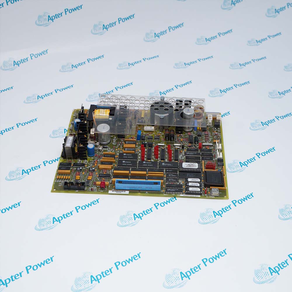
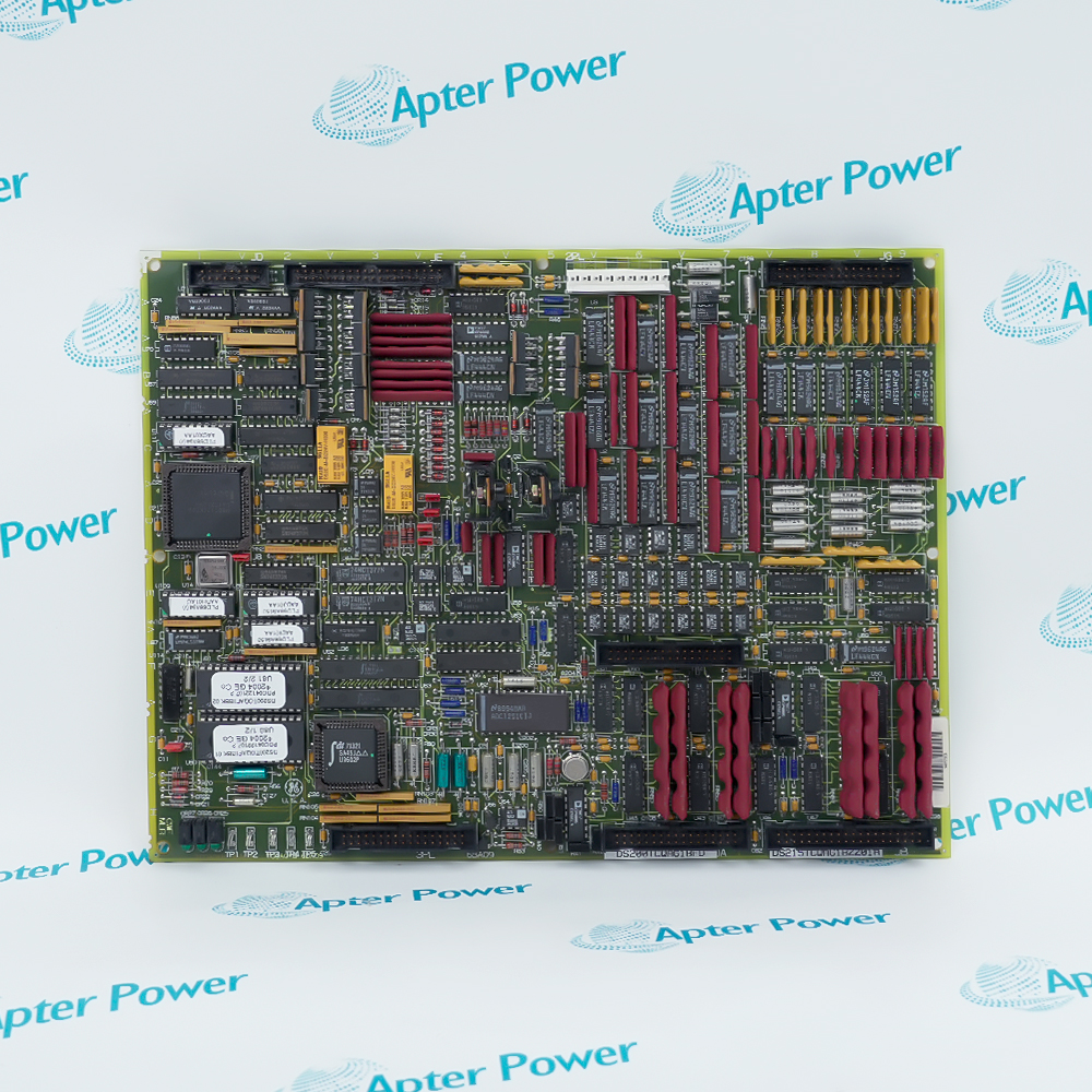
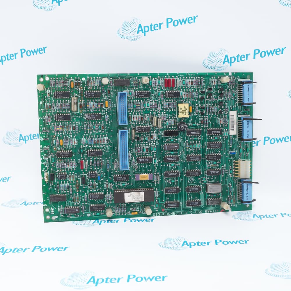
General Electric DS200FGPAG1A is an LCI gate pulse amplifier board with two gate channels, optical command and status paths, and onboard control-power conversion.
In Stock
Ships by Thursday, October 29
Fast Shipping Available
Get a quick price for DS200FGPAG1A
Quantity
*E-mail
Company
*Mobile
*Content
Upload (gif, jpg, jpeg, png, bmp, doc, docx, xls, xlsx, ppt, pdf, csv)

Technical specifications for DS200FGPAG1A

  • Manufacturer:
    General Electric
  • Part Number:
    DS200FGPAG1A
  • Product Family:
    GE Mark V/VI Driver Board
  • Product Type:
    Gate Pulse Amplifier Board
  • Stock:
    1
  • Bridge requirement:
    Three FGPA boards per 3-phase SCR bridge
  • Gate-driver circuits:
    Two identical circuits per board
  • SCR gating capacity:
    One to six series-connected SCRs per gate driver
  • Status monitoring:
    Optical inputs from 2 to 12 FHVA boards
  • Fiber-optic I/O:
    14 receivers and one transmitter
  • Gate pedestal current:
    20 to 25 A peak
  • Backporch output:
    5 A AC to FHVA; approximately 1 A DC at SCR
  • Status output:
    12 SCR bits plus one power-supply status bit
  • Tariff Code:
    8504909000
  • Country of origin:
    USA
  • Place of shipment:
    Xiamen, Fujian, China
By purchasing this item, you agree to the Terms & Conditions, ApterPower is not an authorized distributor for listed manufacturers or tradenames and therefore the manufacturer's warranty does not apply. All our products come with ApterPower's 1-year warranty.

More Information

Overview Manuals Gate Drive Fiber Status Power Rails Board Service

Features:

  • Two gate-driver channels on one board supply the A and B paths for a single SCR-bridge phase.
  • Each gate driver can energize the isolation-current-transformer chain for one to six series-connected SCRs.
  • Fourteen optical receivers and one optical transmitter separate firing commands from cell and supply status.
The gate pedestal supplies the initial 20 to 25 A peak, after which the backporch stage maintains 5 A rms at the FGPA output for the remainder of the command.

U101 and U201 receive the two gate commands, U301-U312 collect the FHVA cell indications, and U318 returns the multiplexed status word to the control.

P5, P40, and P90 are supervised by the undervoltage logic; P15 is available as a separate auxiliary level but is not monitored.

The General Electric DS200FGPAG1A Gate Pulse Amplifier Board may still be available for purchase and support from Apter Power beyond End-Of-Life (EOL) by the manufacturer (OEM).
General Electric DS200FGPAG1A Gate Pulse Amplifier Board Manuals,Datasheets,Link Important Notice: Other accessories, manuals, cables, calibration data, software, etc. are not included with this equipment unless listed in the above stock item description. All prices are shown in USD.

Matching the port to the external device

  • Gate A command: U101 / AGATEIN receives the channel-A optical firing command
  • Gate B command: U201 / BGATEIN receives the channel-B optical firing command
  • Gate A output: E101 AGATE1 and E102 AGATE2 feed the FHVA transformer loop; E103 is AGND
  • Gate B output: E201 BGATE1 and E202 BGATE2 feed the second loop; E203 is BGND

Matching the port to the external device

  • Cell inputs: U301-U312 receive blocking-state light from as many as twelve FHVA channels
  • Return link: U318 transmits twelve SCR status bits plus switching-supply status
  • State meaning: Received light indicates that the monitored SCR is blocking voltage
  • Cable arrangement: U101/U201 are designed for a duplex command cable; cell-status connectors are simplex

Matching the port to the external device

  • P5: 4.7-5.1 V dc logic supply
  • P40: 25 V dc gate-backporch supply point
  • P90: 81 V dc gate-pedestal supply point
  • P15: Typically 13.5-14.5 V dc and not included in undervoltage monitoring

Matching the port to the external device

  • Service scope: The board has no fuses or other end-user-serviceable parts
  • Power isolation: Turn power off and verify that no voltage remains before touching the board
  • Handling: Use a grounding strap and store the board in an antistatic bag or box
  • Identification: Record the full part number, equipment order data, LCI model, and board description
Description
General Electric DS200FGPAG1A is a Gate Pulse Amplifier Board serving one phase of an LCI SCR bridge. Two gate-driver circuits translate optical firing commands into isolated gate power for the series-connected SCRs.

Within DS200FGPAG1A, a charged pedestal pulse starts conduction and the regulated backporch current maintains the gate command for its remaining duration. The gate current travels through the isolation transformers mounted on the associated FHVA boards.

Cell-blocking indications from the FHVA boards are multiplexed by DS200FGPAG1A and returned to the control over a serial optical link together with its power-supply status. The on-board switching supply provides the control voltages used by both gating and status functions.
Alternative Names
DS200FGPAG1A DS200-FGPA-G1A DS200 FGPA G1A GE DS200FGPAG1A General Electric DS200FGPAG1A FGPA Gate Pulse Amplifier Board DS200FGPA G1A LS2100 DS200FGPAG1A
Technical notes
The P15 auxiliary supply on DS200FGPAG1A is not included in the board’s undervoltage monitoring. Measure it separately when the monitored P5, P40, and P90 rails appear normal but gate or status behavior remains abnormal.
Exceptional Service

Our Mission

  • 100% Satisfaction

    We believe expertise is priceless. With over 20 years of experience, and top engineers on staff, we can help you solve or avoid problems that threaten your business.
  • Trust Guaranteed

    Not only do we have a vast inventory, our team makes sure every piece of equipment is in working condition. Your purchases are also backed by our Warranty.
  • Expertise

    Time is money, especially when your equipment is down. We work quickly to get your equipment on its way so you can get it back up and running.

FAQS

The following is a list of questions commonly asked by our customers. Please contact us if you have a question about our process that is not answered below.
Why can DS200FGPAG1A receive a gate command but produce no SCR gate current?
On DS200FGPAG1A, the U101 or U201 command receiver and the matching AGATE or BGATE power output are separate stages; verify supply and trace both stages.
When only some series-connected SCRs fail to turn on, how should DS200FGPAG1A be checked?
Each DS200FGPAG1A driver can feed one to six FHVA isolation transformers in series, so inspect the complete conductor loop and every series connection.
If DS200FGPAG1A still gates normally, why can SCR cell status disappear?
The DS200FGPAG1A command and return fibers are separate; loss at U301–U312 or U318 can remove status without stopping gate commands.
What should be measured when DS200FGPAG1A reports a supply undervoltage?
Measure the monitored P5, P40, and P90 rails on DS200FGPAG1A, then check P15 separately because that auxiliary rail is not monitored.
How can crossed fibers be prevented during a DS200FGPAG1A replacement?
Keep the DS200FGPAG1A command pair at U101 and U201, return each status fiber to U301–U312, and reserve U318 for outgoing status.
Before DS200FGPAG1A is removed, which handling mistake must be avoided?
Power must be verified absent before DS200FGPAG1A removal, and optical connectors should be released by their bodies rather than pulled by the fibers.
Which records reduce the risk of ordering the wrong DS200FGPAG1A?
Match DS200FGPAG1A by its complete stamped number, LCI identity, bridge phase, fiber assignments, and gate-stab connections rather than by board appearance.