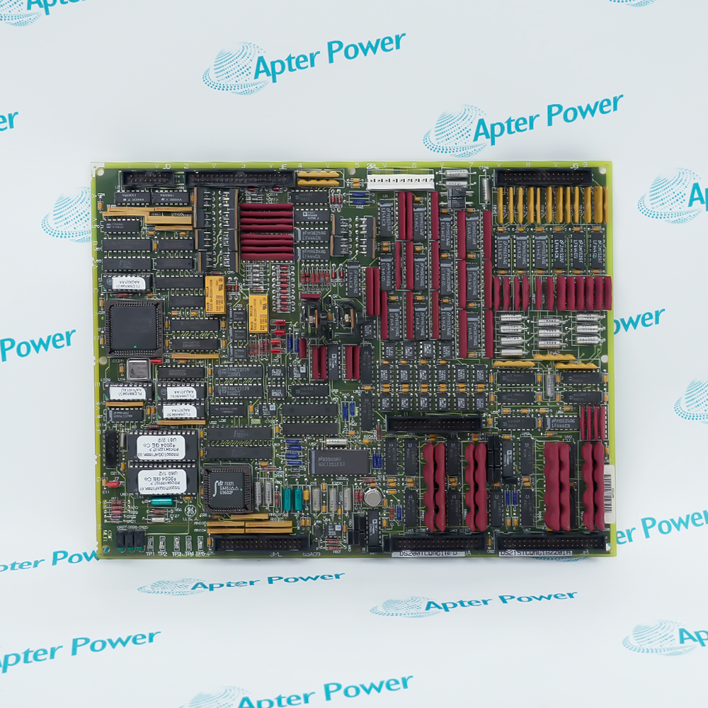
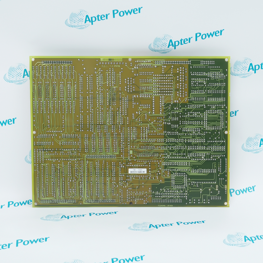
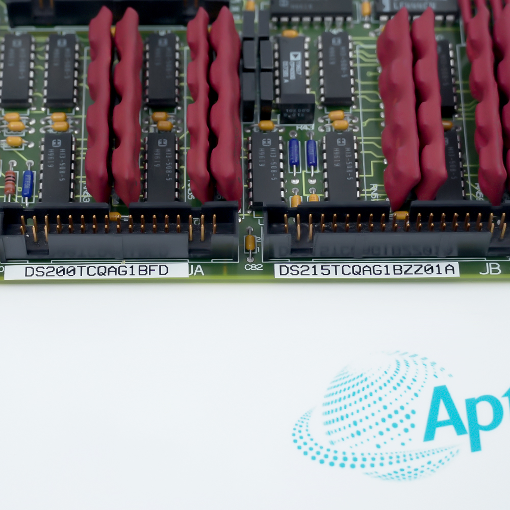
DS200TCQAG1BFD DS215TCQAG1BZZ01A
Ask our team:
  • Phone: +86 181 0690 9650
  • E-Mail info@apterpower.com
  • Lifecycle status

    Discontinued / Obsolete by OEM
    Apter Power offers quotations, technical data and system-matching support for General Electric DS200TCQAG1BFD DS215TCQAG1BZZ01A.

DS200TCQAG1BFD DS215TCQAG1BZZ01A

/ 4.9
1001 reviews | Need a Specific Revision?
General Electric DS200TCQAG1BFD DS215TCQAG1BZZ01A is one Mark V TCQA analog I/O board that conditions and routes turbine-control field signals within an R1, R2 or R3 core.
In Stock
Ships by Tuesday, September 29
Fast Shipping Available
Get a quick price for DS200TCQAG1BFD DS215TCQAG1BZZ01A
Quantity
*E-mail
Company
*Mobile
*Content
Upload (gif, jpg, jpeg, png, bmp, doc, docx, xls, xlsx, ppt, pdf, csv)

Technical specifications for DS200TCQAG1BFD DS215TCQAG1BZZ01A

  • Manufacturer:
    General Electric
  • Part Number:
    DS200TCQAG1BFD DS215TCQAG1BZZ01A
  • Product Family:
    GE Mark V/VI Driver Board
  • Product Type:
    TCQA Analog I/O Board
  • Stock:
    1
  • Board Designation:
    TCQA
  • Installed Cores:
    R1, R2 or R3
  • Power Connection:
    2PL
  • Data Bus Connection:
    3PL
  • Analog Reference Test Point:
    TP1, 0 V
  • Current Output Range Selection:
    20 mA or 200 mA via J5 and J6
  • Test Interface:
    RS232 via J7
  • Oscillator Connection:
    J8
  • Trip Signal Connector:
    JD in the R1 core
  • Position Input Connector:
    JF from TBQC
  • Weight:
    1.28 lbs (0.58 kg)
  • Estimated shipping dimensions:
    28x21.2x2.5 cm
  • Tariff Code:
    8537101190
  • Country of origin:
    USA
  • Place of shipment:
    Xiamen,Fujian,China
By purchasing this item, you agree to the Terms & Conditions, ApterPower is not an authorized distributor for listed manufacturers or tradenames and therefore the manufacturer's warranty does not apply. All our products come with ApterPower's 1-year warranty.

More Information

Overview Manuals Signal Inputs Output Paths Core Connections Configuration

Features:

  • Pairs a DS200 base-board code with a DS215 assembly identifier.
  • Conditions analog measurements from three Mark V terminal boards.
  • Separates field inputs, board data and control-command paths.
DS200TCQAG1BFD and DS215TCQAG1BZZ01A identify the same TCQA hardware rather than two independent boards.

The installed core determines which generator, line and trip-related interconnections participate in the signal path.

Independent terminal-board routes allow temperature, current, motion and vibration channels to be traced by signal family.

The General Electric DS200TCQAG1BFD DS215TCQAG1BZZ01A TCQA Analog I/O Board may still be available for purchase and support from Apter Power beyond End-Of-Life (EOL) by the manufacturer (OEM).
General Electric DS200TCQAG1BFD DS215TCQAG1BZZ01A TCQA Analog I/O Board Manuals,Datasheets,Link Important Notice: Other accessories, manuals, cables, calibration data, software, etc. are not included with this equipment unless listed in the above stock item description. All prices are shown in USD.

Terminal-Board Measurement Paths

  • JA: Thermocouple inputs and cold-junction compensation from TBQA.
  • JB: Current-loop circuits associated with TBQC.
  • JF: LVDT and LVDR position inputs from TBQC.
  • JG: Seismic vibration and voltage inputs from TBQB.

Command and Feedback Flow

  • Current Loops: 4–20 mA outputs return through the TBQC connection.
  • Servo Commands: Servo outputs pass through JE and TCQC.
  • Relay Drivers: Relay-driver commands share the JE route.
  • Trip Route: JD is assigned in R1 and unused in R2 or R3.

Power and Data Interconnections

  • 2PL: Distributes TCPS power to the TCQA board.
  • 3PL in R2/R3: Links STCA with the installed TCQA board.
  • 3PL in R1: Places STCA, TCQA and TCQE on the shared bus.
  • R1 Feedback: Generator and line signals use the TCQC path.

Hardware Selection Points

  • J1 and J2: Select the two current-output circuits.
  • J5 and J6: Set the current-output maximum to 20 mA or 200 mA.
  • J7: Provides the RS232 test connection.
  • J8: Connects the board oscillator.
Description
General Electric DS200TCQAG1BFD DS215TCQAG1BZZ01A is one TCQA Analog I/O Board for the Mark V turbine control system. DS200TCQAG1BFD identifies the base-board configuration, while DS215TCQAG1BZZ01A appears as the paired assembly identifier on the same hardware.

The signal chain through DS200TCQAG1BFD DS215TCQAG1BZZ01A begins at the TBQA, TBQB and TBQC terminal boards. Temperature, current-loop, position, vibration and voltage information is separated into dedicated input paths, conditioned on the TCQA board and exchanged with STCA over the control-core data bus.

Core placement changes part of the routing for DS200TCQAG1BFD DS215TCQAG1BZZ01A. In R1, the shared data path also involves TCQE and includes generator, line and trip-related connections, whereas the trip connection is not used when the same TCQA board occupies R2 or R3.

Two current-output circuits on DS200TCQAG1BFD DS215TCQAG1BZZ01A have independent hardware selections for circuit enablement and maximum output. Separate connections provide the analog reference, board test interface and oscillator path without combining those functions with the field-signal terminals.
Alternative Names
GE DS200TCQAG1BFD DS215TCQAG1BZZ01A DS200 TCQA G1B FD DS215 TCQA G1B ZZ01A General Electric TCQA DS200TCQAG1BFD DS215TCQAG1BZZ01A DS200TCQAG1B-FD DS215TCQAG1B-ZZ01A Mark V TCQA Analog I/O Board FD ZZ01A GE Mark V DS200 TCQA FD DS215 TCQA ZZ01A DS200 TCQA Board with DS215 TCQA Assembly DS2O0TCQAG1BFD DS215TCQAG1BZZO1A
Technical notes
General Electric DS200TCQAG1BFD and DS215TCQAG1BZZ01A are paired identifiers on one Mark V TCQA analog I/O board; both complete codes should be matched.
Exceptional Service

Our Mission

  • 100% Satisfaction

    We believe expertise is priceless. With over 20 years of experience, and top engineers on staff, we can help you solve or avoid problems that threaten your business.
  • Trust Guaranteed

    Not only do we have a vast inventory, our team makes sure every piece of equipment is in working condition. Your purchases are also backed by our Warranty.
  • Expertise

    Time is money, especially when your equipment is down. We work quickly to get your equipment on its way so you can get it back up and running.

FAQS

The following is a list of questions commonly asked by our customers. Please contact us if you have a question about our process that is not answered below.
Why do DS200TCQAG1BFD and DS215TCQAG1BZZ01A appear on the same TCQA board?
DS200TCQAG1BFD identifies the base-board configuration and DS215TCQAG1BZZ01A is the paired assembly identifier, so both complete codes belong to the same TCQA hardware.
Which core assignment must be checked before reconnecting DS200TCQAG1BFD DS215TCQAG1BZZ01A?
The R1 installation of DS200TCQAG1BFD DS215TCQAG1BZZ01A includes TCQE on the shared data route and uses trip, generator and line paths that are not assigned identically in R2 or R3.
How can missing thermocouple and current-loop groups be separated on DS200TCQAG1BFD DS215TCQAG1BZZ01A?
Thermocouple channels reach DS200TCQAG1BFD DS215TCQAG1BZZ01A through JA from TBQA, while current-loop channels use JB through TBQC; comparing those paths narrows the missing group.
What should be reviewed if a current output from DS200TCQAG1BFD DS215TCQAG1BZZ01A stops at the wrong level?
J5 and J6 on DS200TCQAG1BFD DS215TCQAG1BZZ01A select a 20 mA or 200 mA ceiling for the respective output circuit, so the jumper position must match the intended loop.
Where is the analog reference checked during DS200TCQAG1BFD DS215TCQAG1BZZ01A signal testing?
TP1 is the 0 V analog reference on DS200TCQAG1BFD DS215TCQAG1BZZ01A and provides the common point for comparing board-level analog measurements.
Why can DS200TCQAG1BFD DS215TCQAG1BZZ01A retain analog inputs while servo or relay commands are absent?
The input connectors and the JE command route are separate on DS200TCQAG1BFD DS215TCQAG1BZZ01A; servo and relay-driver outputs must pass through JE and TCQC even when input conditioning remains active.