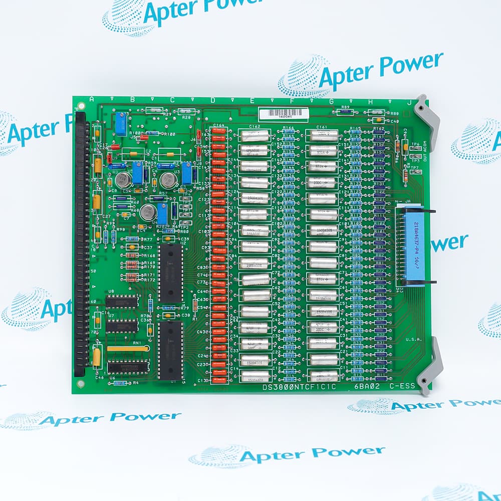
Features:
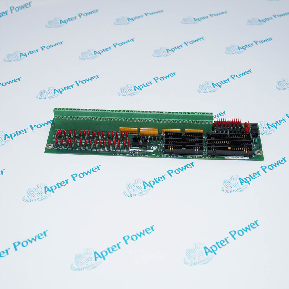
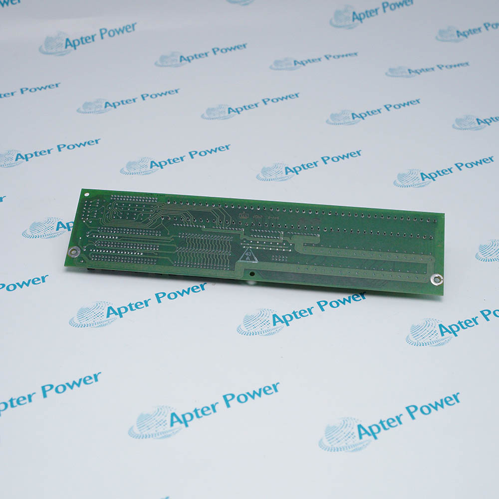
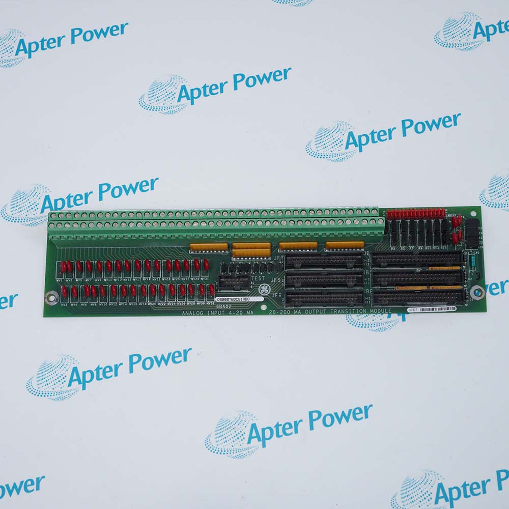
- Mark V LM termination role: Connects current-loop, position-feedback, and milliamp-output wiring to the TCQA board in the assigned core.
- Multi-signal support: Handles 4–20 mA inputs, LVDT/R position inputs, and two selectable current outputs.
- Core placement: The TBQC board occupies location 9 in the <R1>, <R2>, or <R3> core.
The board consolidates analog field wiring before signals enter the TCQA processing path, keeping current-loop and position-feedback connections organized by core.
Separate JBR and JFR paths distinguish current-related traffic from LVDT/R position feedback, supporting clearer cable identification during sourcing and service.
Hardware jumpers define input grounding and output-current limits, so the installed settings remain part of the exact configuration record.
For the General Electric DS200TBQCG1A Analog Input and Milliamp I/O Termination Module, Apter Power provides quotation, documentation, and installed-system matching support.
General Electric DS200TBQCG1A Analog Input and Milliamp I/O Termination Module Manuals,Datasheets,Link
Important Notice: Other accessories, manuals, cables, calibration data, software, etc. are not included with this equipment unless listed in the above stock item description. All prices are shown in USD.
- 4–20 mA input path: JBR carries the fifteen field-current inputs from TBQC to TCQA.
- Milliamp output path: JBR returns two current-output signals from TCQA to the termination module.
- Position-feedback path: JFR carries LVDT/R position inputs from TBQC to TCQA.
- Normally unused connectors: JBS/T, JFS/T, and TEST help distinguish the active cable set from spare connection points.
- Input grounding: BJ1 through BJ15 connect milliamp inputs 1 through 15 to DCOM when fitted.
- Output 1 range: BJ16 selects a 20 mA or 200 mA maximum for the first current output.
- Output 2 range: BJ17 selects a 20 mA or 200 mA maximum for the second current output.
- Configuration record: Retaining the installed jumper pattern supports accurate replacement selection without assuming another cabinet uses the same settings.
- Complete revision: The DS200TBQCG1AAA or DS200TBQCG1ABB marking helps Apter Power identify the requested board version.
- Core position: Location 9 in the <R1>, <R2>, or <R3> core identifies the board’s installed Mark V LM context.
- Output-range setting: The BJ16 and BJ17 positions show whether each current output uses a 20 mA or 200 mA maximum.
- Cable map: A JBR and JFR connection record helps Apter Power review the installed signal path before shipment.
- Process-current inputs: Terminates fifteen 4–20 mA field signals for TCQA processing.
- Position feedback: Connects LVDT/R position signals used in Mark V LM control functions.
- Low-current output: Supports a current-output circuit configured for a 20 mA maximum.
- High-current output: Supports a current-output circuit configured for a 200 mA maximum.