Features:
- Direct or reverse indication for each discrete input
- Internal excitation or an external 18-30 VDC field supply
- 5 ms +/-20% input filtering and isolation delay
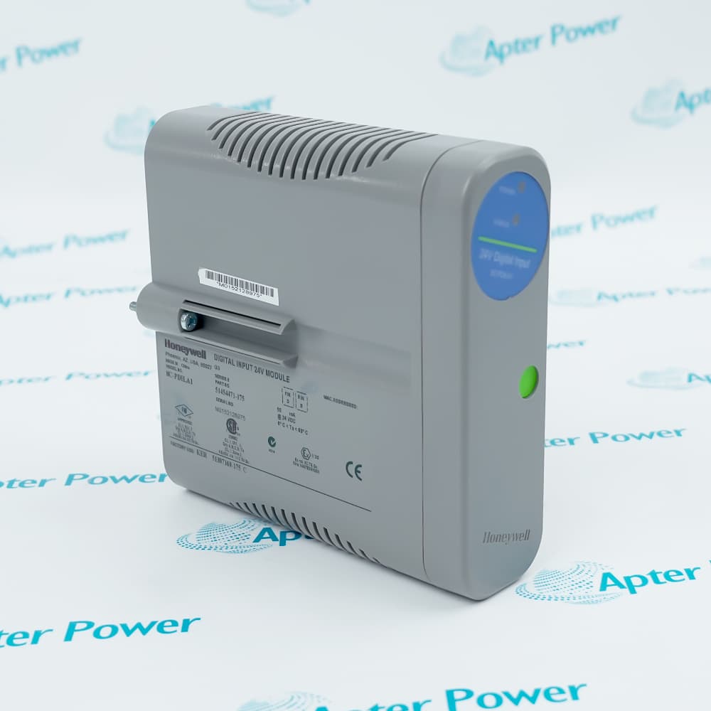
A field contact connected to 8C-PDILA1 51454471-175 is evaluated against defined ON and OFF thresholds before its state reaches the Series 8 control strategy. The module recognizes ON at 13 VDC or 3 mA minimum and OFF at 5 VDC or 1.2 mA maximum.
Direct and reverse indication let the reported logic state follow the required contact convention. The 4.2 kohm input path also separates field sensing from module logic through optical isolation.
Excitation can be supplied internally or from an external 18-30 VDC source. Selecting external power provides system-to-field galvanic isolation and changes how the input commons are wired.
The Honeywell 8C-PDILA1 51454471-175 Digital Input Module is listed as Active / Available from OEM. Apter Power can assist with product inquiries and access to available Honeywell documentation.
Honeywell 8C-PDILA1 51454471-175 Digital Input 24VDC, Coated Manuals, Datasheets, Links
Important Notice: Other accessories, manuals, cables, calibration data, software, etc. are not included with this equipment unless listed in the above stock item description. All prices are shown in USD.
Termination and redundancy:
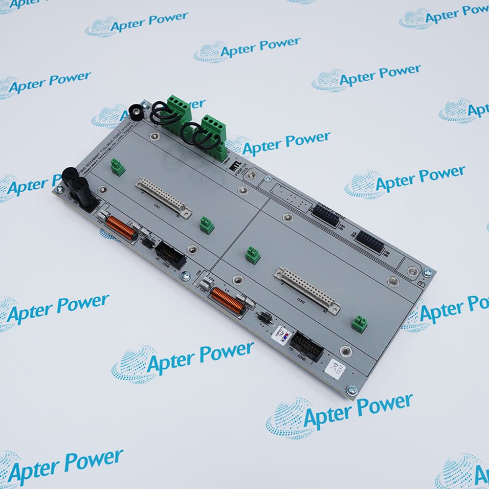
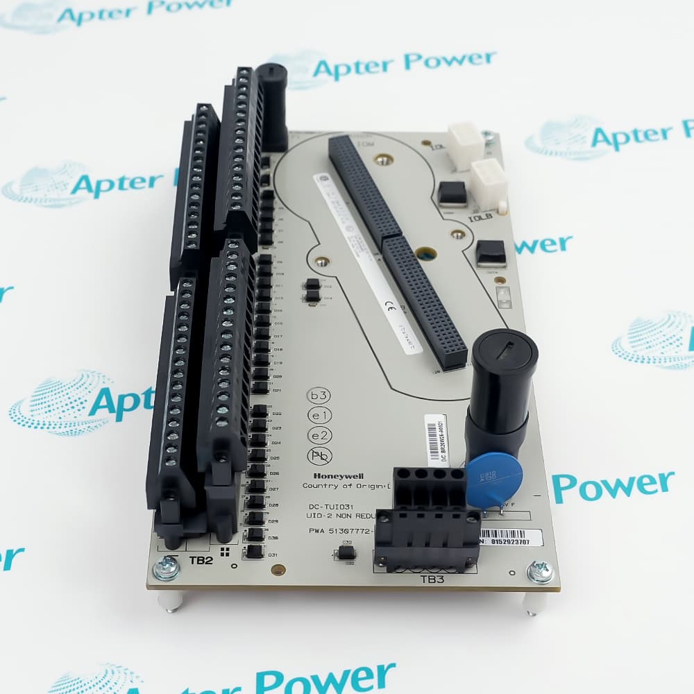
- Single path: 8C-TDILA1 is the coated 9-inch non-redundant IOTA for 8C-PDILA1 51454471-175.
- Redundant path: 8C-TDILB1 is the coated 12-inch IOTA for redundant operation.
- Channel count: Both arrangements terminate the module's 32 standard digital inputs.
- Maintenance: Removal and insertion of the input module under power is supported.
Discrete-state thresholds:
- ON state: 8C-PDILA1 51454471-175 recognizes 13 VDC or 3 mA minimum.
- OFF state: The channel recognizes 5 VDC or 1.2 mA maximum as OFF.
- Input impedance: Each sensing channel presents 4.2 kΩ.
- Filter delay: Input filtering and isolation add 5 ms ±20% absolute delay.
Input-path checks:
- Data integrity: 8C-PDILA1 51454471-175 includes internal diagnostics for discrete input acquisition.
- ON resistance: Guaranteed ON requires field resistance no greater than 300 Ω at 15 VDC.
- OFF resistance: Guaranteed OFF requires at least 30 kΩ field resistance at 30 VDC.
- Optical barrier: The IOM uses optical isolation between field sensing and the module logic path.
Excitation arrangements:
- Internal source: Onboard excitation lets 8C-PDILA1 51454471-175 operate without separate marshalling power.
- External source: User-supplied field power is accepted from 18 to 30 VDC.
- Isolation condition: System-to-field galvanic isolation is available when external field power is used.
- Signal direction: Direct or reverse indication adapts the logic state to the field-contact convention.
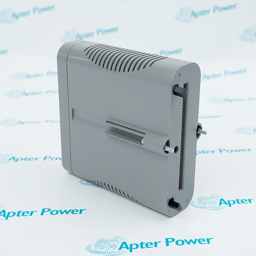
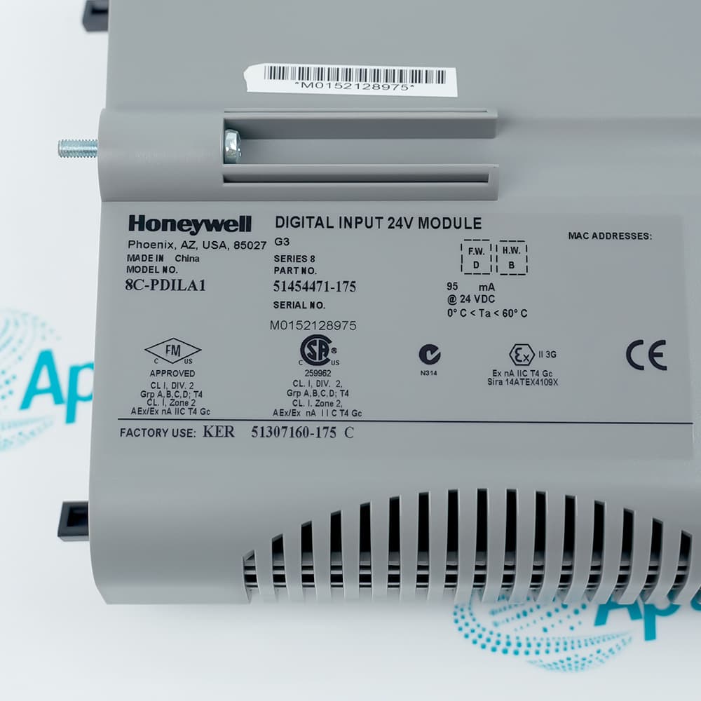

 Honeywell 8C-PDILA1 51454471-175 Datasheet