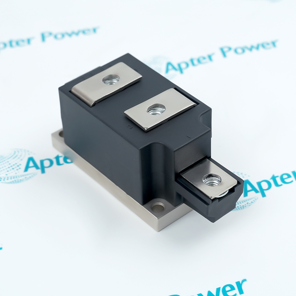
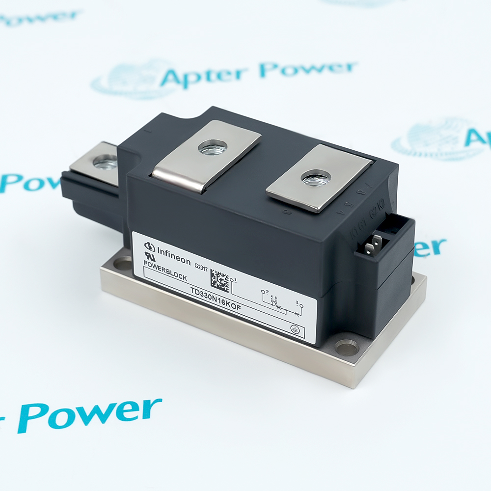
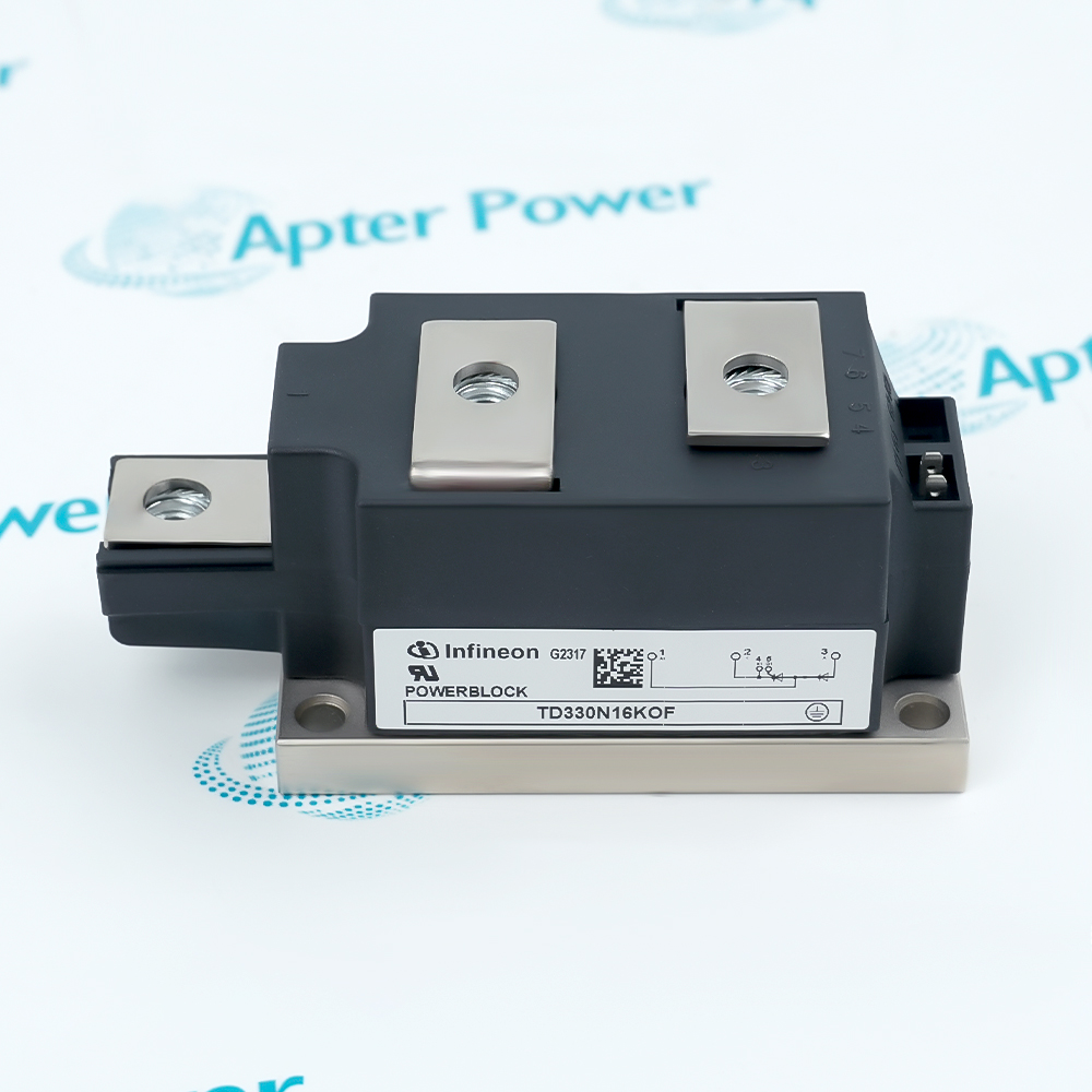
Features:
- Combines a phase-control thyristor and diode in one 1600 V insulated power block.
- Carries 330 A average on-state current when case temperature remains at the specified condition.
- Transfers semiconductor losses through an isolated baseplate secured by the documented mounting torque.
Infineon TD330N16KOF separates its high-current power terminals from the low-energy gate connection.
The thyristor controls the conduction interval while the diode completes the specified rectifier arrangement.
Electrical loss, thermal resistance and heat-sink contact must be evaluated as one operating system.
The Infineon TD330N16KOF 1600 V 330 A Thyristor/Diode Power Module is listed by the OEM as active and preferred.
Infineon TD330N16KOF Thyristor/Diode Module Manuals,Datasheets,Link
Important Notice: Other accessories, manuals, cables, calibration data, software, etc. are not included with this equipment unless listed in the above stock item description. All prices are shown in USD.
Thyristor–Diode Conduction Sequence
- Controlled arm: A gate pulse starts current in the thyristor arm at the selected point in the AC cycle.
- Uncontrolled arm: The diode conducts according to circuit polarity and does not require a separate trigger.
- Off-state duty: The repetitive blocking rating applies while the relevant semiconductor arm is not conducting.
- Current classes: Continuous average current and short non-repetitive surge current describe different loading intervals.
Heat Flow from Junction to Heat Sink
- Conduction loss: Threshold voltage and slope resistance combine with the load waveform to determine on-state loss.
- Dual heat source: The thyristor and diode junctions contribute heat to the common module base.
- Insulated transfer: Heat crosses the electrically insulated baseplate before entering the external heat sink.
- Interface pressure: Correct mounting torque keeps the baseplate in uniform contact with the thermal interface material.
- Junction limit: The completed cooling path must hold both semiconductor junctions within the specified temperature boundary.
Trigger and Transient Coordination
- Gate drive: The trigger circuit must provide the documented gate current and voltage between gate and cathode.
- Cathode reference: The control connection is electrically distinct from the main terminals but remains referenced to the thyristor cathode.
- Current rise: Circuit inductance and drive timing must keep turn-on di/dt within the device limit.
- Voltage rise: The surrounding snubber and commutation network must keep off-state dv/dt within its separate limit.
Mechanical and Electrical Interfaces
- Heat-sink face: The isolated baseplate requires a flat, clean mounting surface and an even thermal interface.
- Base fastening: Mounting hardware is tightened to 5 Nm to establish the specified mechanical contact.
- Power joints: Main-current conductors use the larger terminals and the separate 12 Nm terminal torque.
- Control tabs: Gate and auxiliary wiring connect through the 2.8 x 0.8 mm flat terminals rather than the power studs.