Features:
- PROFIBUS connects SIMOVERT MASTERDRIVES to higher-level automation systems.
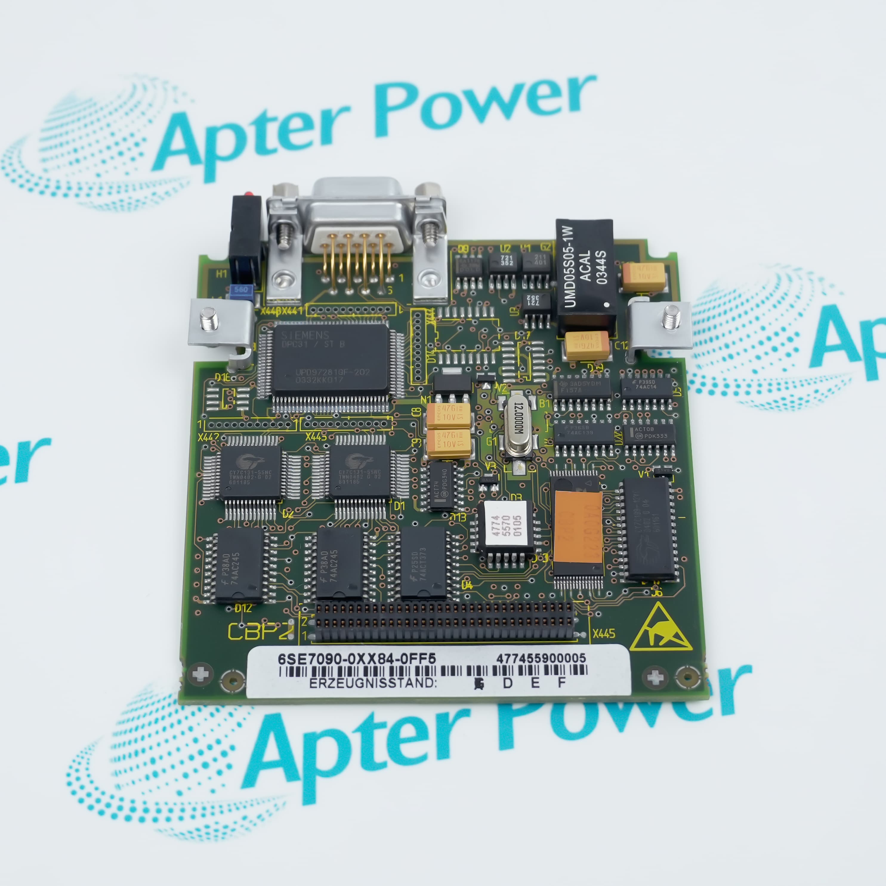
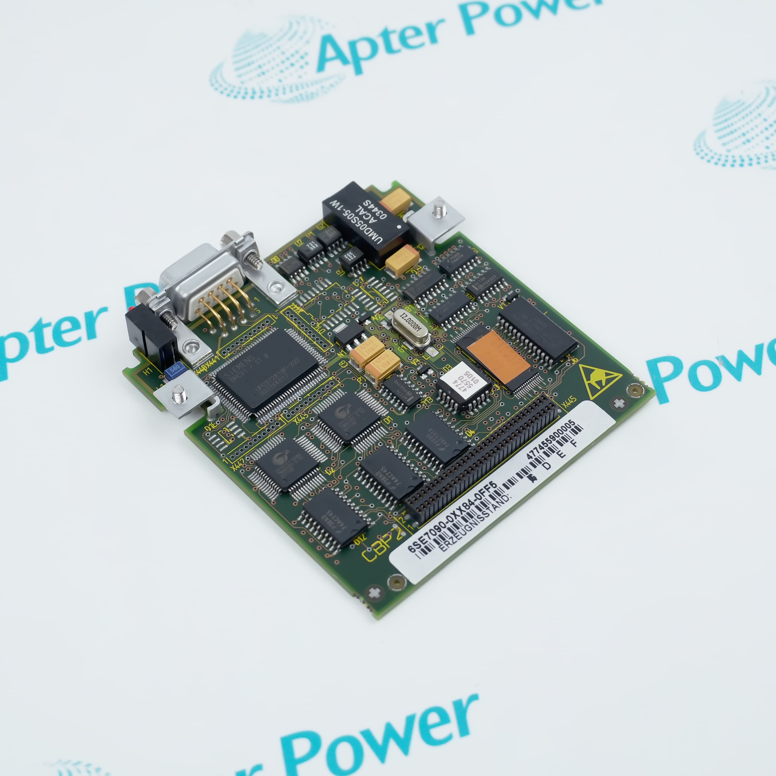
- The X448 9-pole Sub-D interface carries the fieldbus connection.
- Green, yellow and red LEDs report the board operating state.
Siemens 6SE7090-0XX84-0FF5 adds an addressed fieldbus endpoint to a SIMOVERT MASTERDRIVES unit, allowing cyclic process data and parameter access to share one PROFIBUS link.
The telegram separates PKW parameter information from PZD process values, so the supervisory master can configure each data area for the required control task.
The drive supplies the option board internally, while an isolated interface supply on X448 can support bus termination or an Optical Link Plug where the mechanical format permits it.
The Siemens 6SE7090-0XX84-0FF5 CBP2 PROFIBUS Communication Board may still be available for purchase and support from Apter Power beyond End-Of-Life (EOL) by the manufacturer (OEM).
Siemens 6SE7090-0XX84-0FF5 CBP2 PROFIBUS Communication Board Manuals,Datasheets,Link
Important Notice: Other accessories, manuals, cables, calibration data, software, etc. are not included with this equipment unless listed in the above stock item description. All prices are shown in USD.
PROFIBUS Data Exchange
- Slave relationship: The CBP2 presents the connected drive as a PROFIBUS slave to the automation master.
- Bus connector: Network conductors and termination connect through the 9-pole Sub-D X448 interface.
- Transfer rate: The board follows the master-selected bus speed at rates up to 12 MBaud.
- Termination power: An isolated 5 V output on X448 pin 6 can energize the bus terminator.
Telegram and Address Setup
- PKW area: Parameter requests and responses occupy the configurable parameter section of the telegram.
- PZD area: Commands, setpoints, status and actual values use the process-data section.
- Station address: The slave address must be unique on the connected PROFIBUS segment.
- Failure monitoring: The telegram-failure time determines how the drive reacts when cyclic communication stops.
Board-State Checks
- LED pattern: Read the green, yellow and red indicators together instead of treating one color as a complete diagnosis.
- Internal power: Confirm the 5 V supply from the basic unit when every board indicator remains dark.
- Bus path: Inspect the X448 cable, connector seating and termination before changing drive parameters.
- Timeout behavior: Compare the configured failure time with the observed communication interruption.
Option-Board Placement
- Slot use: The CBP2 occupies an available option-board position in the MASTERDRIVES electronics box.
- Board envelope: A 90 × 83 mm outline must remain clear of adjacent components and cable bends.
- Multiple boards: Up to two CBP boards can be fitted in one supported device.
- Compact restriction: An Optical Link Plug cannot be installed with Compact units types 1 and 2 because space is insufficient.