GE DS200FCRRG1AKD
GE DS200FCRRG1AKD
GE DS200FCRRG1AKD
GE DS200FCRRG1AKD
GE DS200FCRRG1AKD
GE DS200FCRRG1AKD
Ask our team:
  • Phone: +86 181 0690 9650
  • E-Mail sales1@apterpower.com
How We Verify Your Order
Before dispatch, we confirm the exact model, revision, condition, inspection requirements and shipping documents for your order.
See a real on-site verification case >>

DS200FCRRG1AKD

/ 4.9
1001 reviews | Need a Specific Revision?
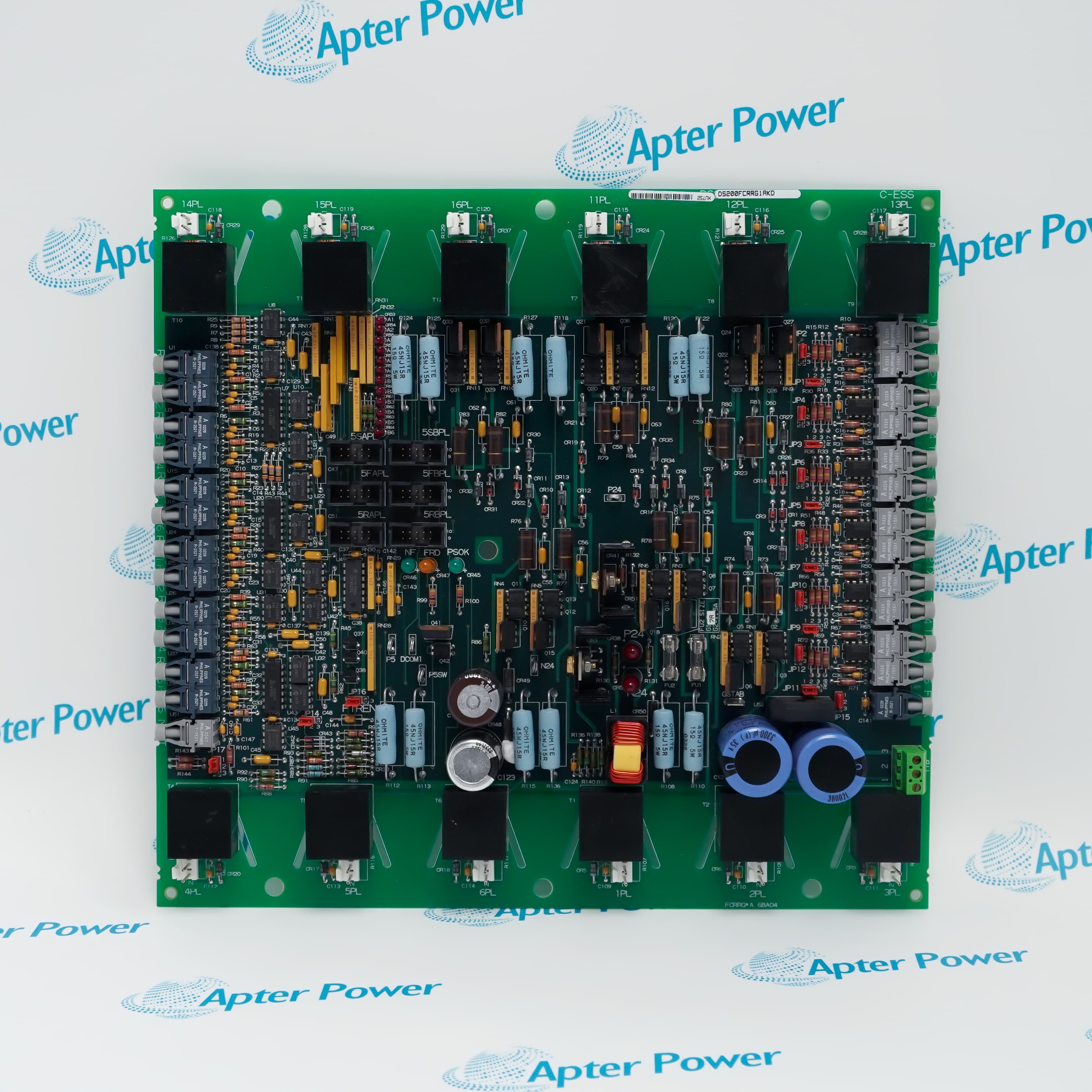
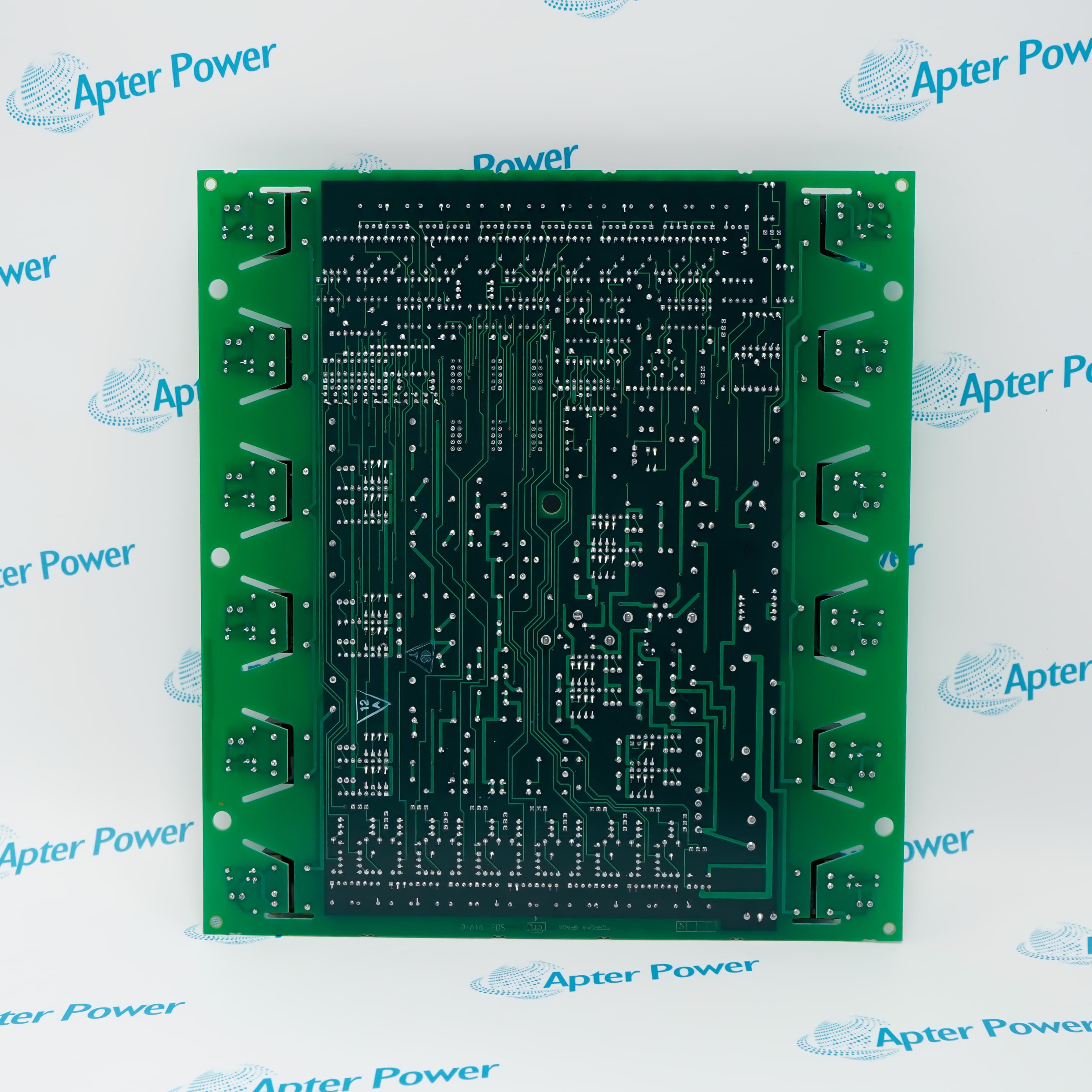
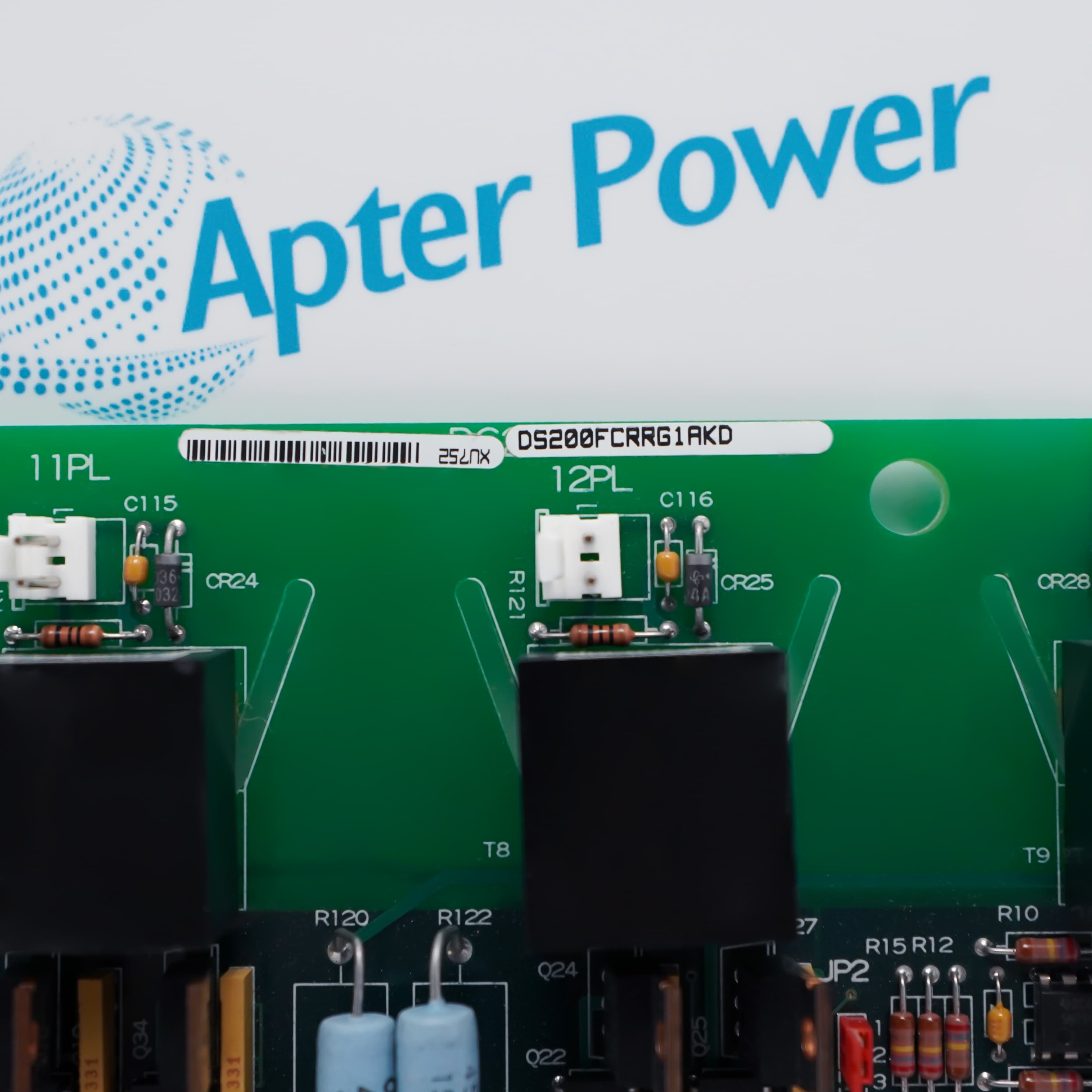
General Electric DS200FCRRG1AKD is an FCRR firing circuit control board that routes drive firing signals through terminal, plug, and ribbon-cable interfaces.
In Stock
Ships by Saturday, November 14
Fast Shipping Available
Get a quick price for DS200FCRRG1AKD
Quantity
*E-mail
Company
*Mobile
*Content
Upload (gif, jpg, jpeg, png, bmp, doc, docx, xls, xlsx, ppt, pdf, csv)

Technical specifications for DS200FCRRG1AKD

  • Manufacturer:
    General Electric
  • Part Number:
    DS200FCRRG1AKD
  • Product Family:
    GE Mark V/VI Driver Board
  • Product Type:
    Firing Circuit Control Board
  • Stock:
    1
  • Terminal Block Capacity:
    95 signal wires
  • Two-Pin Connectors:
    10
  • Connector Designations:
    1PL–6PL and 11PL–16PL
  • Ribbon Cables:
    2
  • Programmable Logic:
    Onboard programmable logic device
  • Dimensions:
    29.3 × 27.0 × 3.3 cm
  • Weight:
    0.84 kg
  • Tariff Code:
    8538900000
  • Country of origin:
    USA
  • Place of shipment:
    Xiamen, Fujian, China
By purchasing this item, you agree to the Terms & Conditions, ApterPower is not an authorized distributor for listed manufacturers or tradenames and therefore the manufacturer's warranty does not apply. All our products come with ApterPower's 1-year warranty.

More Information

Overview Manuals Terminals Connectors Control Application
  • One terminal block for 95 signal wires
  • Ten two-pin PL connectors and two ribbon cables
  • Programmable logic device for the firing-control interface

DS200FCRRG1AKD is a General Electric Firing Circuit Control Board designed for GE Mark V drive-control assemblies.

It organizes firing-control wiring and connector paths between the controller and associated drive circuitry while retaining revision-specific hardware and cable mapping.

Before installation or replacement, verify the terminal schedule, every PL connector location, ribbon-cable orientation, programmable-logic compatibility, revision suffix, wiring tags, and ESD controls.

Availability, condition, price, and shipping time for DS200FCRRG1AKD are confirmed during quotation.

General Electric DS200FCRRG1AKD Firing Circuit Control Board Manuals, Product Family, Links

Important Notice: Other accessories, manuals, cables, calibration data, software, etc. are not included with this equipment unless listed in the above stock item description. All prices are shown in USD.

  • Terminal block accepts 95 signal wires
  • Conductor positions must follow the drive drawing
  • Shield, common, and signal tags must be preserved
  • Ten two-pin PL connectors
  • Positions span 1PL–6PL and 11PL–16PL
  • Two ribbon cables require correct polarization
  • Onboard programmable logic device
  • Firing paths depend on correct plug placement
  • Qualified procedures are required for energized diagnostics
  • Firing-control circuitry in GE Mark V industrial drives
  • Gate-command interfacing in compatible excitation-control cabinets
  • Legacy drive systems using the documented FCRR terminal and PL layout
Description
DS200FCRRG1AKD is a General Electric Firing Circuit Control Board for GE Mark V and legacy drive-control hardware.

The board combines a 95-wire terminal block, ten two-pin PL connectors, two ribbon cables, and programmable logic for the documented firing-control interface.

Before installation or replacement, confirm the complete catalog number, hardware series, compatible equipment, wiring, mounting, and saved configuration.
Alternative Names
DS200FCRRG1AKD GE DS200FCRRG1AKD General Electric DS200FCRRG1AKD GE Mark V DS200FCRRG1AKD GE Speedtronic DS200FCRRG1AKD GE Drive Systems DS200FCRRG1AKD
Technical notes
DS200FCRRG1AKD requires preservation of the 95-wire terminal map, all PL connections, both ribbon cables, programmed-logic identity, and revision-specific wiring; any mismatch can disrupt firing commands.
Exceptional Service

Our Mission

  • 100% Satisfaction

    We believe expertise is priceless. With over 20 years of experience, and top engineers on staff, we can help you solve or avoid problems that threaten your business.
  • Trust Guaranteed

    Not only do we have a vast inventory, our team makes sure every piece of equipment is in working condition. Your purchases are also backed by our Warranty.
  • Expertise

    Time is money, especially when your equipment is down. We work quickly to get your equipment on its way so you can get it back up and running.

FAQS

The following is a list of questions commonly asked by our customers. Please contact us if you have a question about our process that is not answered below.
How should the 95-wire terminal block on General Electric DS200FCRRG1AKD be documented?
Tag every conductor with its terminal number, photograph the landed arrangement, record shield and common connections, and compare the drive wiring drawing before loosening any terminal.
Why are the PL connector designations important on General Electric DS200FCRRG1AKD?
The ten two-pin plugs occupy specific 1PL–6PL and 11PL–16PL positions; swapping them can misroute firing signals and prevent correct drive operation.
What must be checked when reseating the ribbon cables on General Electric DS200FCRRG1AKD?
Inspect polarization, connector latches, pin alignment, cable folds, abrasion, strain, and the original routing away from energized or high-noise conductors.
Can the programmable logic device on General Electric DS200FCRRG1AKD be exchanged independently?
Only with a documented GE service procedure and verified programmed-device identity; a physically compatible device may contain different logic and must not be substituted casually.
What precautions apply before probing General Electric DS200FCRRG1AKD firing circuits?
De-energize and discharge the drive as specified, confirm absence of hazardous voltage, use isolated calibrated equipment, and follow the applicable firing-circuit procedure.
Why might General Electric DS200FCRRG1AKD fail to produce firing activity after replacement?
Check terminal continuity, PL plug placement, ribbon-cable seating, control permissives, programmable-device identity, upstream commands, and associated gate-path hardware.
How should intermittent firing faults associated with General Electric DS200FCRRG1AKD be separated from wiring faults?
Trend the control command and fault event, inspect terminal tightness and cable motion, then compare board signals with the documented upstream and downstream points.