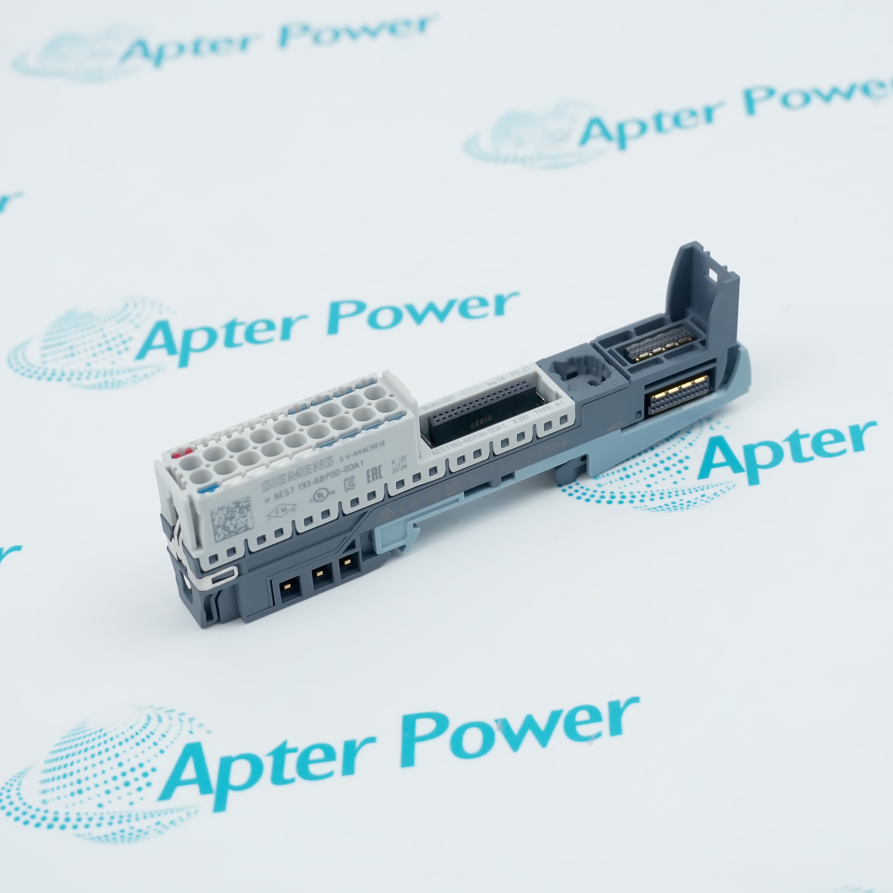
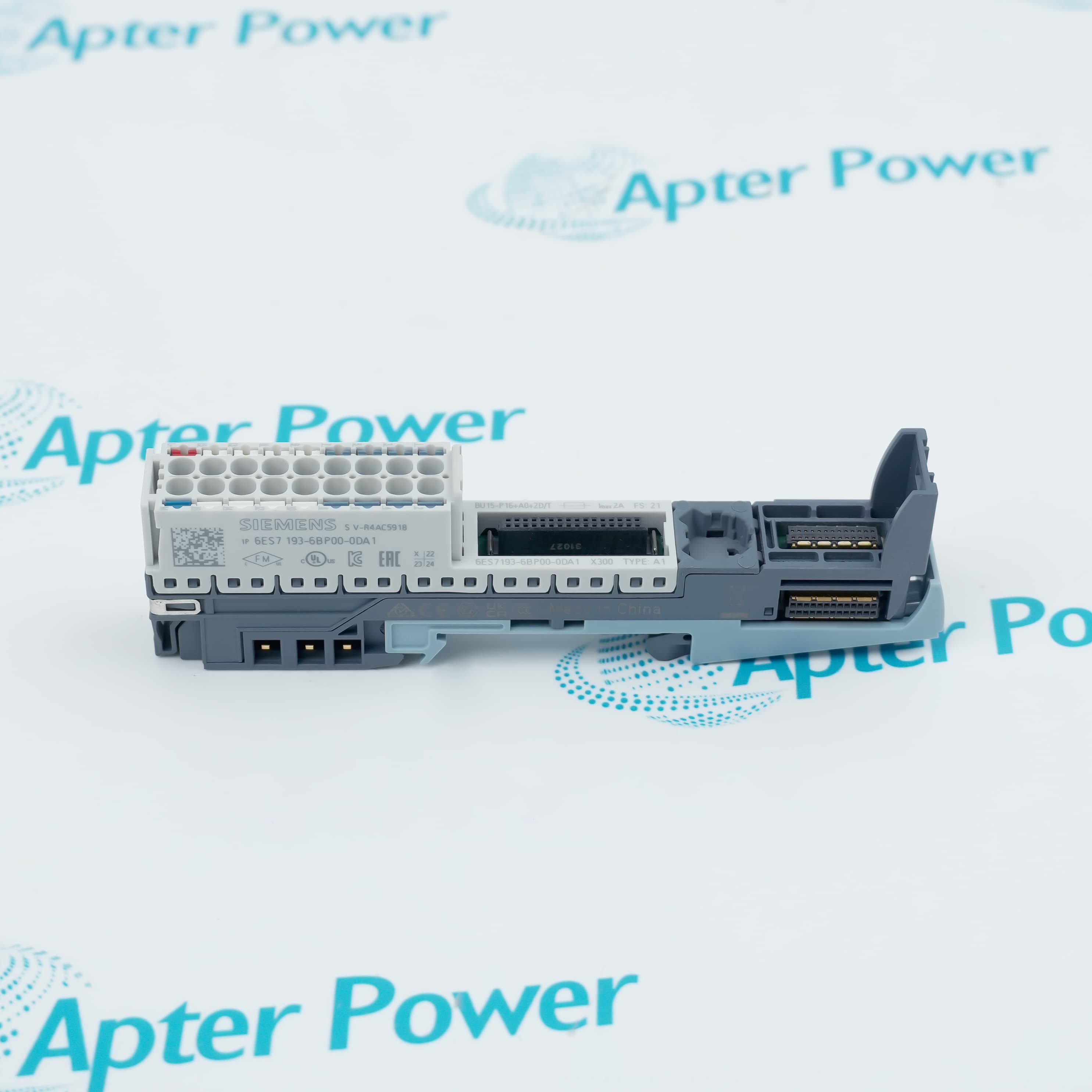
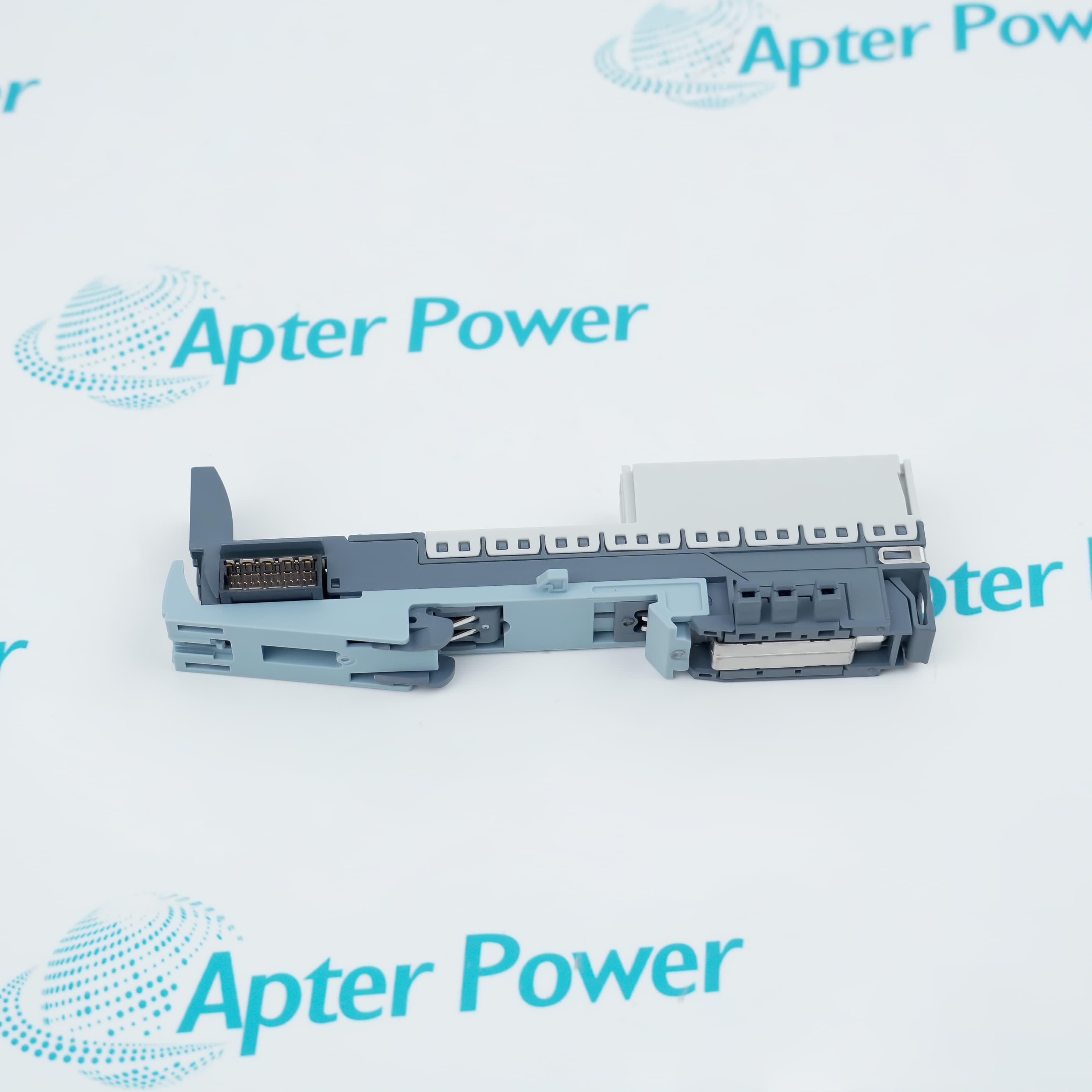
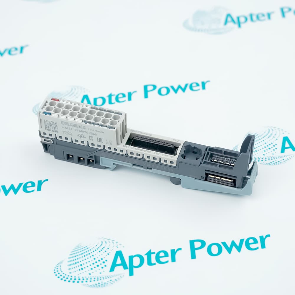
Features:
- BU type A1 construction starts a new SIMATIC ET 200SP potential group.
- Push-in termination provides sixteen process connections in a 15 mm width.
- Integrated temperature acquisition supports compatible analog I/O modules.
Siemens 6ES7193-6BP00-0DA1 places a dedicated termination layer beneath one supported I/O module, keeping field conductors separate from the removable electronics.
Its coded terminal layout omits an AUX bus and opens a fresh potential group, so downstream load-voltage distribution can be organized independently from the preceding group.
For thermocouple measurement, the BaseUnit temperature sensor supplies a local reference-junction value to compatible modules when terminal-temperature compensation is configured.
The Siemens 6ES7193-6BP00-0DA1 SIMATIC ET 200SP BaseUnit is supported with documentation and system-matching assistance from Apter Power.
Siemens 6ES7193-6BP00-0DA1 SIMATIC ET 200SP BaseUnit Manuals,Datasheets,Link
Important Notice: Other accessories, manuals, cables, calibration data, software, etc. are not included with this equipment unless listed in the above stock item description. All prices are shown in USD.
Cabinet Assembly
- Rail position: The 15 mm BaseUnit creates one I/O position on the SIMATIC ET 200SP station rail.
- Wire entry: Push-in contacts accept prepared conductors without terminal screws.
- Shield routing: An optional integrated shield element keeps cable shields close to the field termination.
- Supply protection: A 24 V DC, 10 A breaker with a B or C characteristic protects the incoming lines.
Module and Bus Relationships
- I/O position: One compatible type A1 module is assigned to the BaseUnit.
- Potential grouping: The white BaseUnit begins a new load-voltage group instead of continuing the previous group.
- Backplane path: P1 and P2 pass station power through the BaseUnit with a combined 10 A limit.
- AUX arrangement: No AUX terminals are provided in the BU15-P16+A0+2D/T layout.
Cabinet Conditions
- Horizontal mounting: The permitted ambient range extends from -30 to 60 °C.
- Vertical mounting: The upper ambient limit becomes 50 °C while the lower limit remains -30 °C.
- Altitude planning: Installation is specified to 5,000 m with restrictions above 2,000 m.
- Reference junction: An even temperature around the terminals improves compensation for thermocouple channels.
Supply and Isolation Planning
- Bus loading: Add the downstream P1/P2 demand before confirming that the 10 A path is sufficient.
- Branch current: Each process terminal must remain within its 2 A rating.
- Isolation proof: The BaseUnit is type-tested at 707 V DC.
- Conductor choice: Field wires must stay within 0.14 to 2.5 mm² for reliable push-in contact.