Ask our team:
  • Phone: +86 181 0690 9650
  • E-Mail sales1@apterpower.com
  • Lifecycle status

    Discontinued / Obsolete by OEM
    Apter Power supports sourcing enquiries for this discontinued ABB board.

DATX110 3ASC25H209

/ 4.9
1001 reviews | Need a Specific Revision?
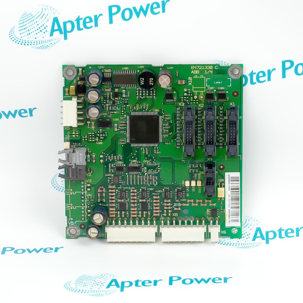
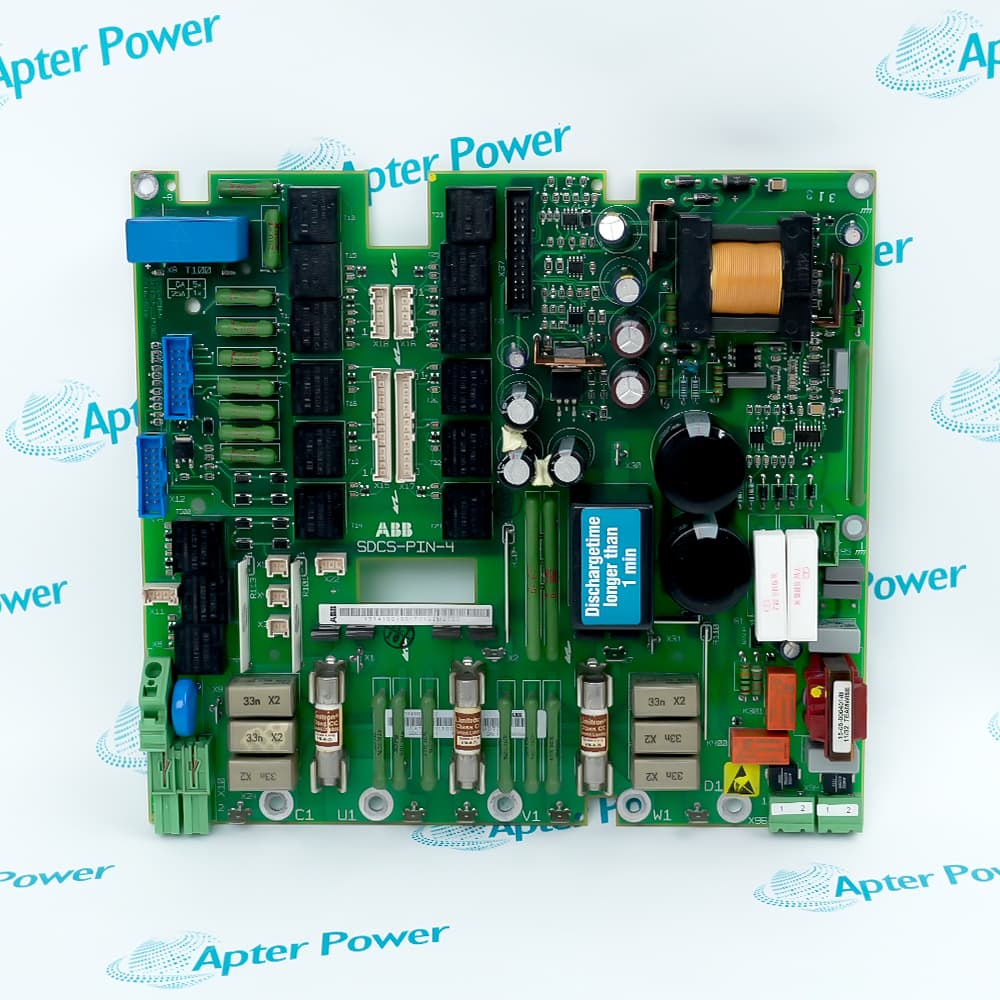
ABB DATX110 3ASC25H209 is a process I/O board connecting field signals to an ASTAT crane-control module.
In Stock
Ships by Friday, October 30
Fast Shipping Available
Get a quick price for DATX110 3ASC25H209
Quantity
*E-mail
Company
*Mobile
*Content
Upload (gif, jpg, jpeg, png, bmp, doc, docx, xls, xlsx, ppt, pdf, csv)

Technical specifications for DATX110 3ASC25H209

  • Manufacturer:
    ABB
  • Part Number:
    DATX110 3ASC25H209
  • Product Family:
    ABB Drives
  • Product Type:
    I/O Board
  • Stock:
    1
  • Digital input circuit:
    110 V DC; galvanically separated; internally supplied detection voltage
  • Relay outputs:
    250 V AC; maximum pull-in current 2 A
  • Analog input resolution:
    11 bits plus one sign bit
  • Analog inputs 1-7:
    Jumper-selectable ±10 V or 0-20 mA
  • Analog input 8:
    Jumper-selectable ±10 V, ±50 V, ±100 V or 0-20 mA
  • Analog outputs:
    Not included in the base part number
  • Tariff Code:
    8538900000
  • Country of origin:
    Sweden
  • Place of shipment:
    Xiamen, Fujian, China
By purchasing this item, you agree to the Terms & Conditions, ApterPower is not an authorized distributor for listed manufacturers or tradenames and therefore the manufacturer's warranty does not apply. All our products come with ApterPower's 1-year warranty.

More Information

Overview Manuals Input Configuration Product Applications Signal Indication Board Servicing

Features:

  • Process I/O combines contact signals, analog inputs and pulse-encoder connections.
  • Selectable input conditioning accommodates voltage and current signals.
  • Relay outputs and channel indicators provide a local interface to crane-control circuits.
DATX110 3ASC25H209 occupies the process-I/O position in the control module. Field connections are grouped by signal function, so contact inputs, measurement signals and encoder wiring remain distinguishable within the assembly.

Hardware-selectable analog conditioning allows the input circuits to serve different instrument interfaces. The selected circuit must follow the connected signal source; software scaling and the physical input selection are separate parts of the setup.

Relay connections provide the output-side interface, while on-board indicators show channel activity. Together they give the technician access to both the incoming field information and the outgoing control signals at the process board.

ABB DATX110 3ASC25H209 I/O Board enquiries can be sent to Apter Power with the installed assembly details and required supply scope.
ABB DATX110 3ASC25H209 I/O Board Manuals,Datasheets,Link
Important Notice: Other accessories, manuals, cables, calibration data, software, etc. are not included with this equipment unless listed in the above stock item description. All prices are shown in USD.
  • Input groups S1-S4 include current-source, shunt and input-ground selections for analog inputs 1-4.
  • Groups S5-S7 select the corresponding current-source, shunt and grounding arrangements for analog inputs 5-7.
  • Match the complete S8/S18 jumper combination to the required analog input 8 tachometer range.
  • The board address is position 1; remote I/O station address settings belong to a different part of the installation.
  • Local process I/O in ASTAT control modules connects field contacts and analog signals to the motion-control system.
  • Crane hoist installations use configuration-dependent input assignments for limit switches, brake feedback and overload contacts.
  • Crane travel installations use a different input assignment map; the terminal plan follows the selected motion and cabin-I/O configuration.
  • Rotor-contactor, cable-reel and thyristor-fan duties can use digital output 1 according to the selected ASTAT function.
  • Yellow DI 1-DI 16 indicators show active digital-input channels.
  • Yellow DO 1-DO 8 indicators show active digital-output channels.
  • Yellow AI 1-AI 4 indicators represent software-controlled analog-input levels rather than a universal analog-signal healthy state.
  • The red ASYM indicator concerns imbalance between two bridges; the red EARTH FAULT indicator concerns the 110 V circuit.
  • DATX110 3ASC25H209 is among the boards whose settings must be recorded before removal.
  • Connector jumper arrangements are part of the installed configuration and must be restored where fitted.
  • Replacement-board handling requires protection against electrostatic discharge and mechanical damage.
  • Commissioning checks include the actual digital-input and PTC circuits, rather than board appearance alone.
Description
DATX110 3ASC25H209 brings discrete machine states, continuous reference signals and encoder feedback into the same ASTAT process interface. These signal types have different jobs: a contact represents a switching condition, an analog input carries a varying value, and encoder channels convey motion feedback. Their combination lets the control module work with the different forms of information present on a crane.

The galvanically separated digital-input circuits on DATX110 3ASC25H209 use internally supplied detection voltage. Field-contact information crosses an electrical isolation boundary before it is used by the control system. This circuit arrangement is an important part of the interface design, not an indication that the external wiring or its power arrangements can be treated as interchangeable.

Relay outputs give DATX110 3ASC25H209 an interface to external relay and contactor coils. The board carries control commands to those devices rather than supplying the driven motor itself. This separation between signal processing, auxiliary switching and the power circuit gives maintenance teams a clear starting point when tracing a command through the installation.
Alternative Names
DATX 110 3ASC25H209 DATXII0 3ASC25H209 DATX11O 3ASC25H2O9 DATX100 3ASC25H209 DATX110+AO+PU 3ASC25H209+AO+PU DATX111 3ASC25H224 DATX120 3ASC25H210
Technical notes
DATX110 3ASC25H209 has a revision-dependent encoder supply limit: PR:A permits 200 mA, while PR:B and newer permit 500 mA. Compare the fitted board revision with the encoder's current demand before replacement. A matching connector or the presence of a 24 V supply does not establish adequate current capacity.
Exceptional Service

Our Mission

  • 100% Satisfaction

    We believe expertise is priceless. With over 20 years of experience, and top engineers on staff, we can help you solve or avoid problems that threaten your business.
  • Trust Guaranteed

    Not only do we have a vast inventory, our team makes sure every piece of equipment is in working condition. Your purchases are also backed by our Warranty.
  • Expertise

    Time is money, especially when your equipment is down. We work quickly to get your equipment on its way so you can get it back up and running.

FAQS

The following is a list of questions commonly asked by our customers. Please contact us if you have a question about our process that is not answered below.
For an analog-output-equipped installation, does a DATX110 3ASC25H209 base spare include all the required hardware?
No. The base spare excludes analog outputs, whereas the separately listed +AO+PU assembly includes an I/O control board and two analog outputs. State whether the purchase is for the base board or the complete equipped assembly; the base part number alone does not specify the additional hardware.
After changing a load cell connected through DATX110 3ASC25H209, is a zero adjustment enough?
No. The ASTAT load-measurement procedure uses two known test weights and their corresponding input values to establish the span as well as zero. This load-function arrangement requires cabin I/O DAPM 100 and is not available for shared-motion drives. Complete the two-point calibration before relying on the displayed load.
Why does the load-cell input on DATX110 3ASC25H209 appear as a speed reference in another installation?
Analog input 5 has different uses according to the ASTAT arrangement. It is used for the load cell in a system with cabin I/O, but for speed reference when the master switch is connected directly to the control-module I/O. Identify the installed control arrangement before reusing another machine's wiring plan.
Can a higher-pulse-rate encoder be connected to DATX110 3ASC25H209 without changing the input settings?
The encoder input has selectable frequency settings for its A, B and zero channels. Check the maximum pulse rate at the machine's operating speed and the corresponding S10-S12 selections. A mechanically suitable encoder is not enough to establish that the existing input settings remain appropriate.
Does an EARTH FAULT indication on DATX110 3ASC25H209 prove that the board has failed?
No. This indication concerns an earth fault in the 110 V circuit, not a conclusive internal-board diagnosis. Record the indication and have qualified personnel follow the ASTAT fault-tracing procedure for the circuit and its connections before deciding to replace the board.
Can I copy the DI 3 and DI 4 wiring from another crane using DATX110 3ASC25H209?
Only after checking the control configuration. In a direct master-switch arrangement these inputs concern zero-position and full-speed commands; with cabin I/O they can select an operator station or parameter sets. Match the installed RUN_TYPE and station-selection arrangement rather than copying terminal numbers alone.