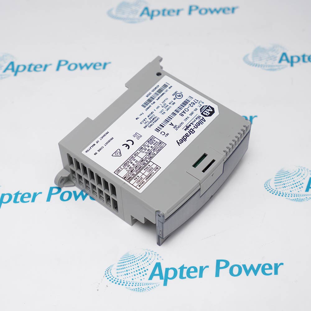
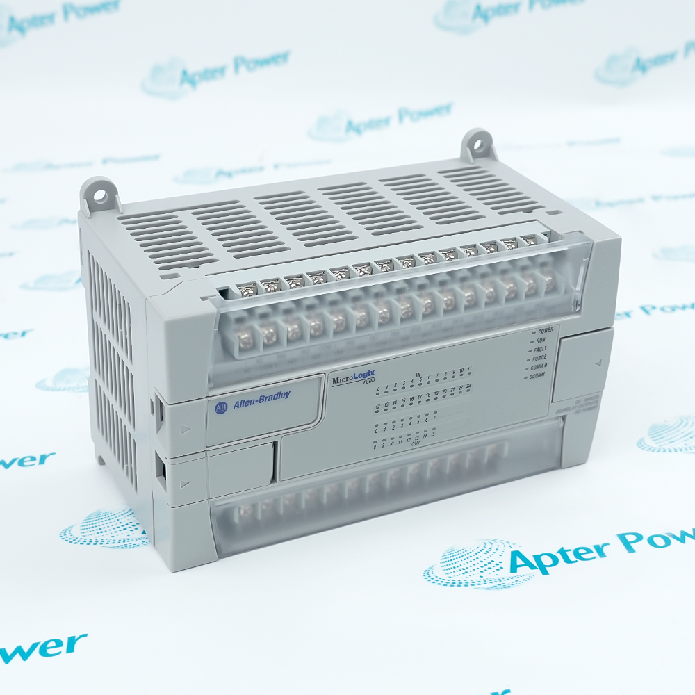
Features:
- Switches eight 24 V DC field loads from one sourcing output group.
- Maps controller output bits 0 through 7 directly to field terminals 0 through 7.
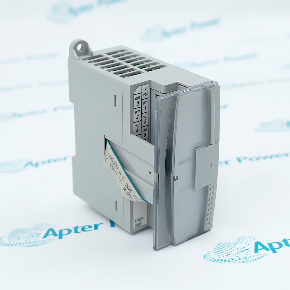
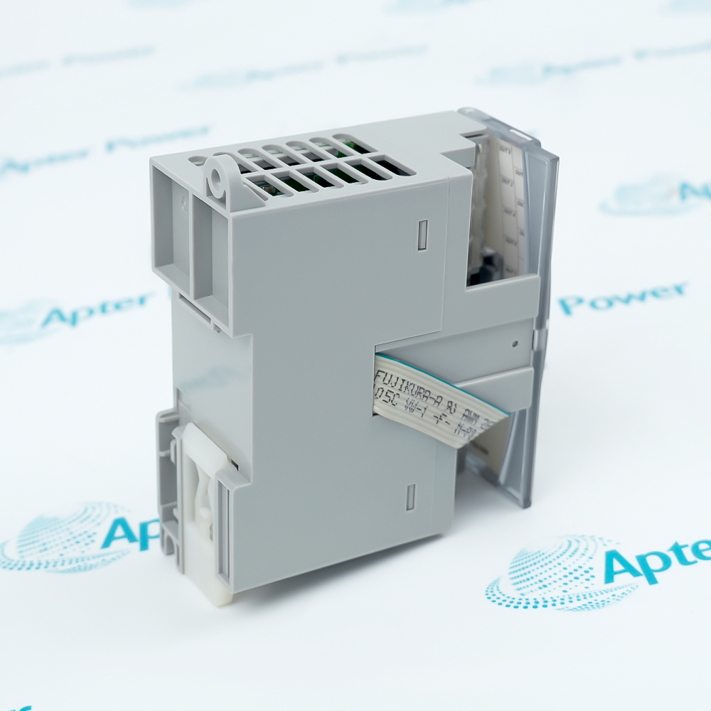
- Uses a removable screw-terminal block and ribbon bus connector in the MicroLogix 1200 expansion assembly.
Allen-Bradley 1762-OB8 receives commanded output states from the MicroLogix 1200 expansion bus and presents them at eight field terminals.
The shared supply and common connections establish one output group, so all eight switched loads reference the same field-power boundary.
Point LEDs, labeled terminals, and the removable terminal block keep controller addressing, field wiring, and visible point state aligned during commissioning.
Allen-Bradley 1762-OB8 Eight-Point 24 V DC Sourcing Solid-State Output Module Manuals,Datasheets,Link
Important Notice: Other accessories, manuals, cables, calibration data, software, etc. are not included with this equipment unless listed in the above stock item description. All prices are shown in USD.
Bit-to-Terminal Organization
- Address map: Output data bits 0 through 7 correspond to terminals OUT 0 through OUT 7.
- Shared supply: The +VDC terminal feeds the common source for all eight solid-state output paths.
- Shared return: DC COM completes the field-power reference for the single output group.
- Group isolation: The complete field group is isolated from the MicroLogix backplane.
Current and Switching Boundaries
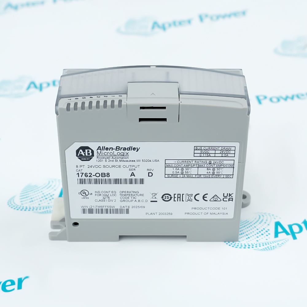
- Point current: Each point carries up to 1 A at 30 °C or 0.5 A at 55 °C.
- Module current: The eight-point group carries up to 8 A at 30 °C or 4 A at 55 °C.
- Switching delay: Resistive-load timing is limited to 0.1 ms on and 1.0 ms off.
- Surge path: A point can carry the documented 2 A surge for 10 ms at the allowed repetition interval.
Controller and Field Separation
- Bus connector: A short ribbon cable connects the module to the adjacent MicroLogix 1200 assembly.
- Bus loading: The module draws its logic power from the 5 V backplane supply.
- State transfer: Controller output words deliver the commanded on or off state to each field point.
- Distance rule: The module position must remain within the six-slot power-supply distance rating.
Terminal and Mounting Practice
- Conductor range: The screw terminals accept the documented solid or stranded copper wire sizes.
- Terminal cover: The fingersafe cover stays in place while conductors are routed under the pressure plates.
- Mounting direction: DIN-rail or panel installation is horizontal only.
- Ventilation space: Clearance around the assembly protects airflow and access to the removable terminal block.