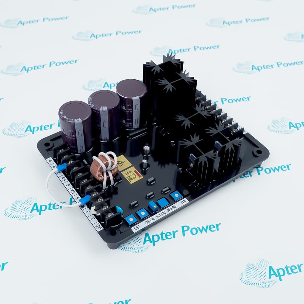
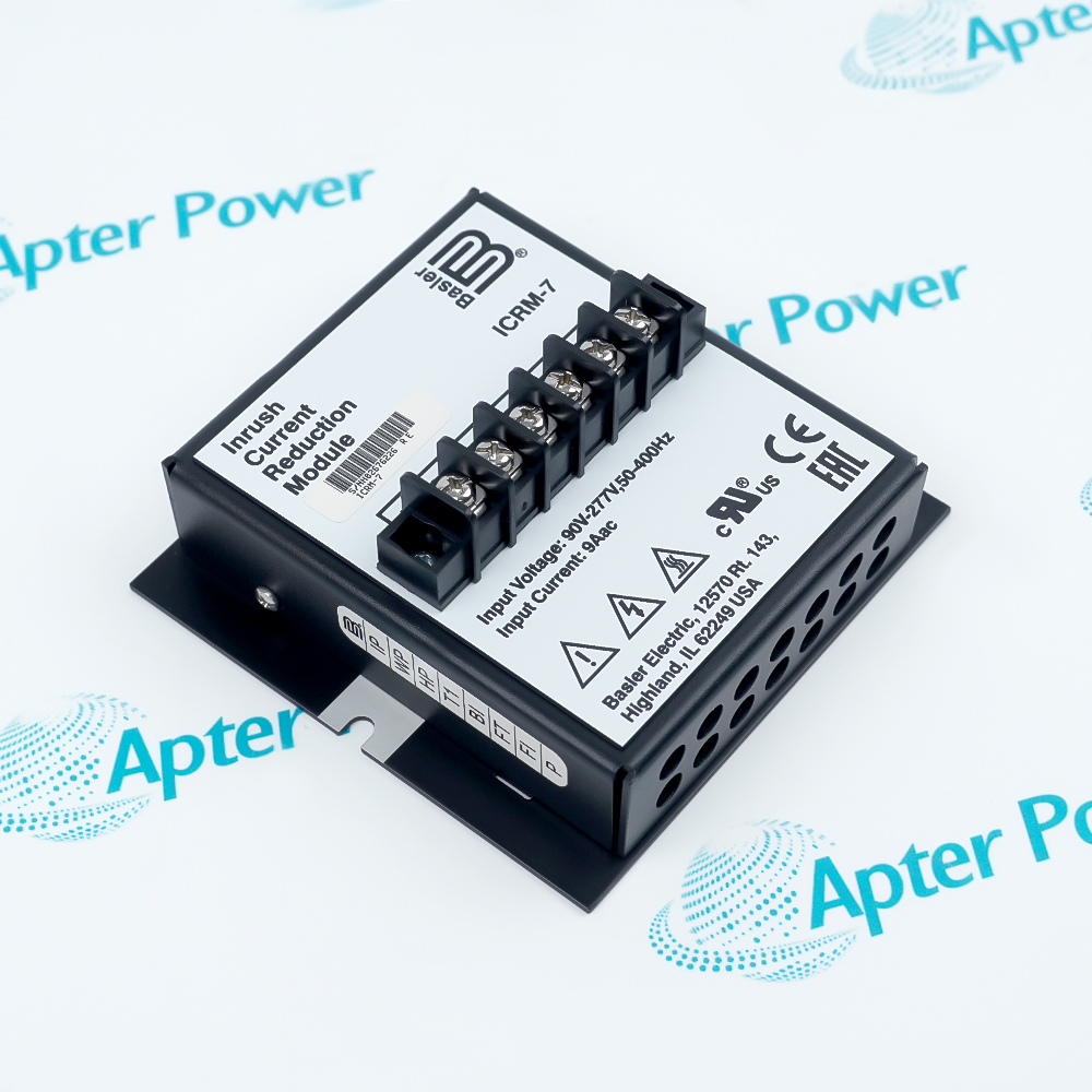
Features:
- Interface Between the Generator Field Winding and Digital Control System
- Combines Capability of Precise Voltage/VAR/PF Regulation with Comprehensive Generator Protection
- Operates in Conjunction with Synchronous Generators and Synchronous Motors
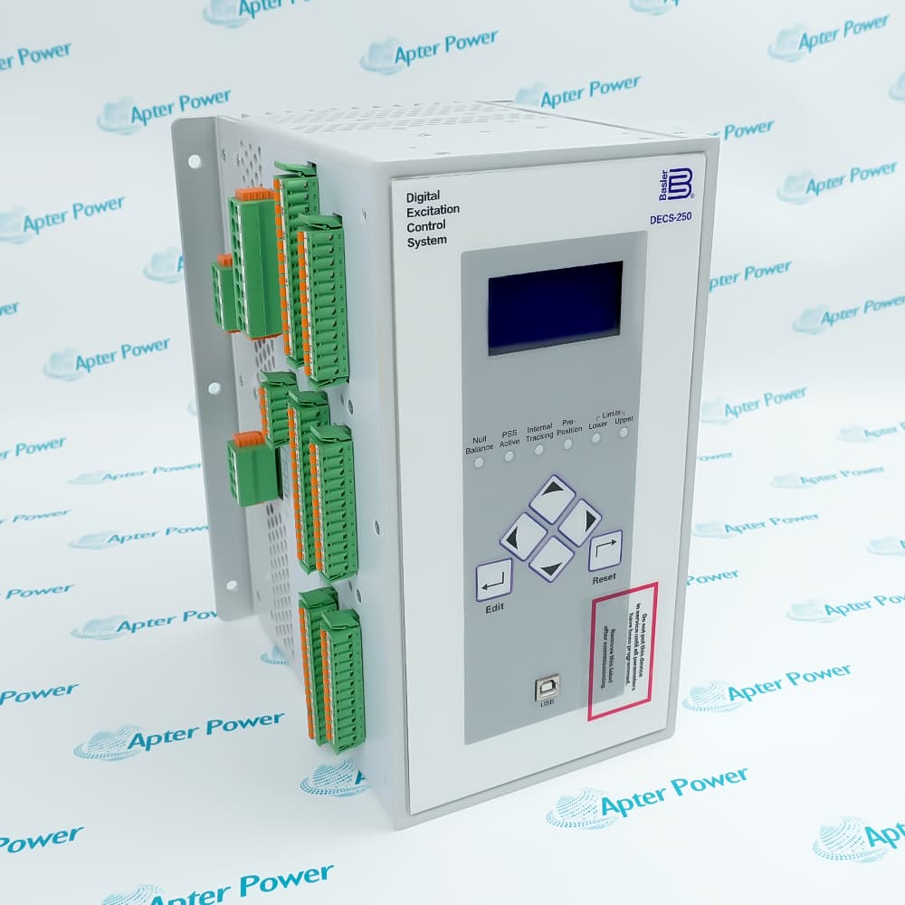
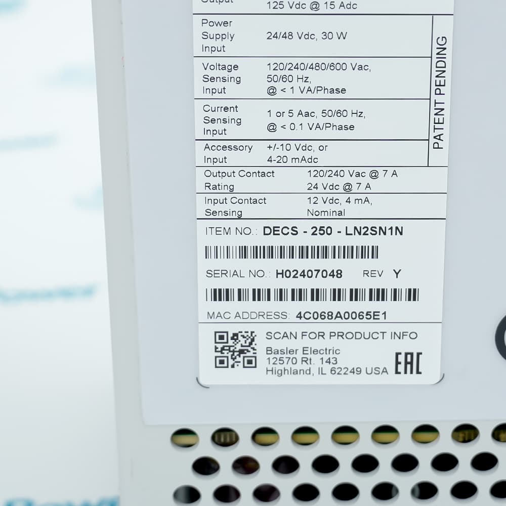
The DECS-250-LN2SN1N operates as the Digital Excitation Control System in a generator control cabinet, providing reliable field current to the generator rotor. It continuously converts incoming DC power (16-60 Vdc) to regulated PWM output and distributes this excitation current through the field circuit to support stable voltage regulation of the generator under all load conditions. Seamless redundancy is available with the DECS-250-LN2SN1N, however using an optional Dual Redundant Configuration will allow seamless switchover to a backup controller in the event of a primary control failure. The DECS-250-LN2SN1N has made improvements in several areas over previous analog excitation designs in addition to incorporating universal input voltage capability within the excitation system.
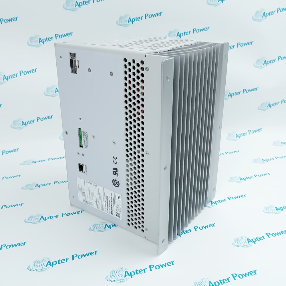
The DECS-250-LN2SN1N provides essential excitation functions common to the entire generator, and is a critical component of the voltage regulation path, directly affecting the proper, normal operation of the overall generator system. One or two DECS-250-LN2SN1N controllers are required per generator depending on the desired redundancy level. The DECS-250-LN2SN1N occupies a compact standalone enclosure in the control cabinet and is always located in the dedicated excitation control position.
For Dual Redundant Control applications, the Generator System requires a second DECS-250-LN2SN1N controller installed in the redundant position. In addition to standard single controller operation, the redundant configuration also performs automatic switchover. The DECS-250-LN2SN1N dual controller configuration executes failover using the internal CAN Bus communication specified in the controller options. Using this method, the redundant control system continually monitors the health of both controllers. If the system detects that the primary DECS-250-LN2SN1N is no longer providing stable output (outside configured voltage/tolerance levels), it will automatically transfer the load to the secondary controller and log an event in the System Event Recorder.
The DECS-250-LN2SN1N Basler Electric Digital Excitation Control System may still be available for purchase and support from Apter Power beyond End-Of-Life (EOL) by the manufacturer (OEM).
Basler Electric DECS-250-LN2SN1N Digital Excitation Control System Manuals, Datasheets, Link
Important Notice: Other accessories, manuals, cables, calibration data, software, etc. are not included with this equipment unless listed in the above stock item description. All prices are shown in USD.
Basler Electric DECS-250-LN2SN1N Digital Excitation Control System Specs
General
- Manufacturer Basler Electric
- Model DECS-250-LN2SN1N
- Condition New Original ready stock
- Product Family DECS-250,DECS–250N,DECS-150
Important Notice: Other accessories, manuals, cables, calibration data, software, etc. are not included with this equipment unless listed in the above stock item description. All prices are shown in USD.
- Power Disconnection: Before performing any wiring operations, all input power and excitation output circuits must be disconnected.
- Physical Fixing: Install the controller in a low-vibration, well-ventilated control cabinet that meets IP20 protection standards.
- Signal Grounding: Ensure the chassis grounding terminal is connected to the main system grounding grid via a low-impedance copper busbar to reduce electromagnetic interference.
- Power Wiring: Connect the single-phase or three-phase AC control power supply according to the drawings and install matching fast-acting fuses for protection.
- Transformer Configuration: Correctly connect the secondary sides of the current transformer (CT) and voltage transformer (PT), ensuring the polarity is not reversed.
- LED Status Indicators: Use the "READY" and "ALARM" indicator lights on the front panel to initially determine the system's operating status.
- Fault Log: Use BESTCOMS Plus software to retrieve the internal event logger and view the timestamped alarm history.
- Waveform Capture: Triggers the built-in oscillator function to analyze voltage and current waveforms under sudden load increases or transient fault conditions.
- Communication Test: Checks the flashing status of the Modbus or Ethernet interface to confirm data synchronization between the controller and the host HMI.
- Hardware Self-Test: Runs a comprehensive self-test program to check the health of the internal microprocessor, memory, and analog input channels.
- Hydropower: Suitable for medium and large-sized hydro turbine generator sets, handling load fluctuations caused by head changes and providing rapid excitation response.
- Thermal Power: Used in combined heat and power (CHP) or industrial self-owned thermal power units to ensure grid voltage stability during sudden large-capacity loads.
- Marine Power: Diesel generator sets deployed on large ships or offshore drilling platforms to meet the requirements of high vibration and complex marine environments.
- Synchronous Condenser: Applied to synchronous condenser systems in new energy reactive power compensation stations, providing transient voltage support and reactive power regulation.