Features:
- Accepts proximity, velocity, and acceleration transducers; channels programmed in pairs; up to two functions per channel pair; multiple static values (Direct, Gap, 1X, 2X, Not 1X, Smax).
- Alert and danger setpoints adjustable 0‑100% of full scale; 4-20 mA recorder outputs per channel (0.3662 μA/bit resolution, 100 ms update); buffered transducer outputs for external analysis.
- ATEX Zone 2, IECEx, Class I Division 2 approvals; operating temperature -30°C to +65°C; 95% non‑condensing humidity; 0.91 kg, 1 front slot.
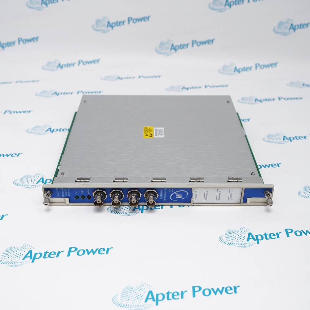
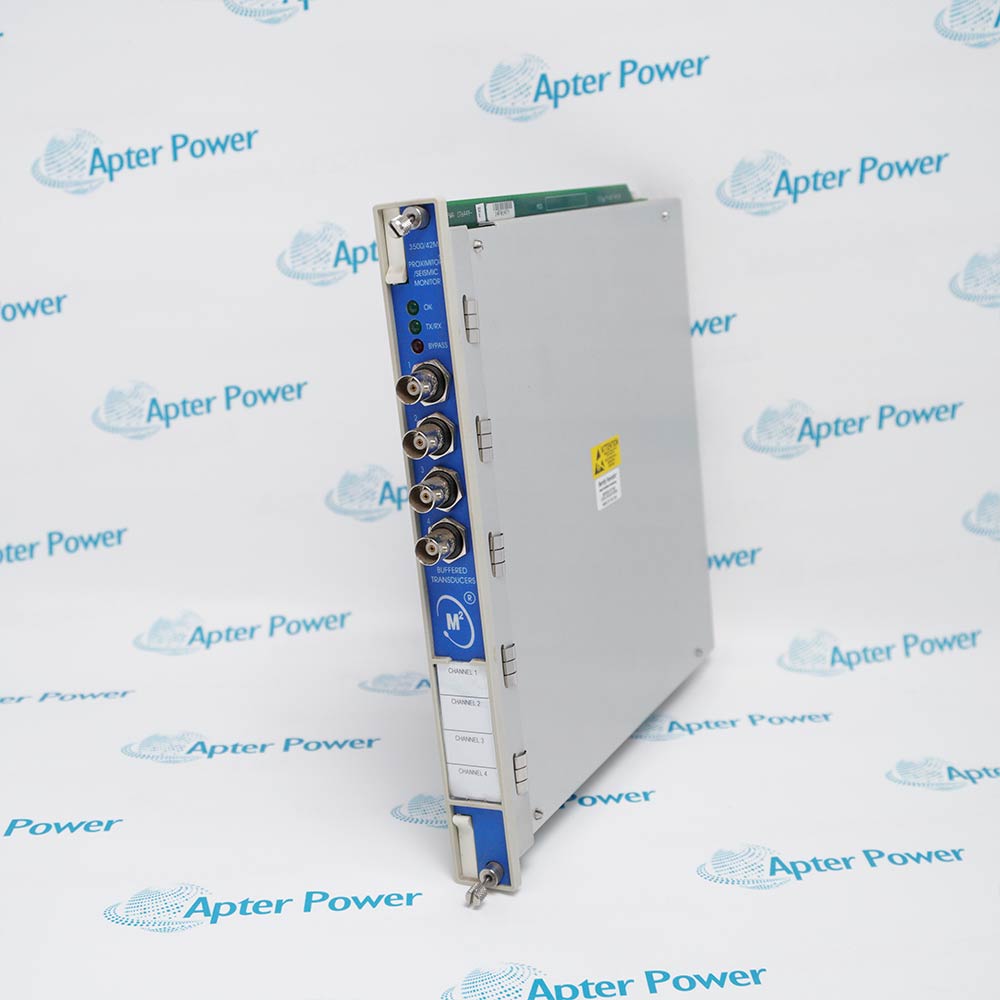
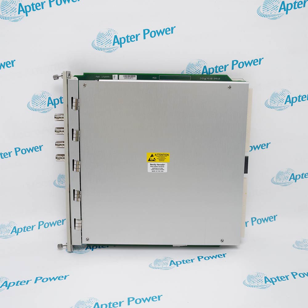
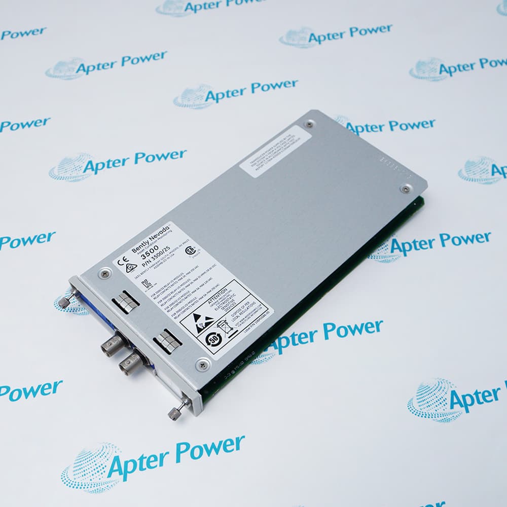
The 3500/42 176449-02 is a versatile four‑channel monitor that accepts inputs from both proximity (eddy current) and seismic (velocity/acceleration) transducers. This allows a single monitor to handle a wide range of machinery protection measurements: radial vibration (shaft relative), thrust position, differential expansion, eccentricity, case vibration (velocity/acceleration), and REBAM (rolling element bearing analysis). Channels are programmed in pairs, and each pair can perform up to two functions simultaneously.
The 3500/42 176449-02 provides comprehensive alarm capabilities essential for machinery protection. Using the 3500 Rack Configuration Software, engineers can set alert setpoints (0‑100% of full scale) for each static value and danger setpoints for any two active static values. Alert delays are adjustable from 1 to 60 seconds in 1‑second intervals; danger delays can be set to 0.1 second or from 1 to 60 seconds in 0.5‑second intervals. This flexibility allows fine‑tuning to avoid nuisance alarms while ensuring rapid response to genuine faults. For integration with plant DCS or PLC systems, each channel provides a 4‑20 mA recorder output proportional to the monitor’s full‑scale measurement.
Industrial machinery is often located in hazardous environments where flammable gases or dust may be present. The 3500/42 176449-02 is certified for use in Class I, Division 2 (cNRTLus) and ATEX/IECEx Zone 2 (Ex nA nC ic IIC T4 Gc) locations when installed with the appropriate I/O modules and per the referenced installation drawings (138547, 149243, 149244). This allows the monitor to be installed directly in the protected area without external barriers, simplifying system design and reducing installation costs.
The 3500/42 176449-02 Bently Nevada Seismic Monitor may still be available for purchase and support from Apter Power beyond
End-Of-Life (EOL)by the manufacturer (OEM).
Bently Nevada 3500/42 176449-02 Seismic Monitor Manuals,
Datasheets,Drivers,Link
Important Notice:Other accessories,manuals,cables,calibration data,software,etc.are not
included with this equipment unless listed in the above stock item description.All prices are
shown in USD.
Bently Nevada 3500/42 176449-02 Seismic Monitor Specs
General
- Manufacturer GE /Bently Nevada
- Model 3500/42 176449-02
- Condition New Original ready stock
- Product Family
3500/40M 176449-01,3500/44M 176449-03
Important Notice:Other accessories,manuals,cables,calibration data,software,etc.are not
included with this equipment unless listed in the above stock item description.All prices are
shown in USD.
- Output Channels: Features 4 analog output channels providing high-resolution signal transmission (typically 14-bit or higher).
- Machinery Protection: Continuously compares real-time vibration levels against configured alarm setpoints to trigger automatic shutdowns or alerts to prevent catastrophic failure.
- Measurement Types: It accepts inputs from proximity and seismic transducers to monitor:Radial Vibration and Thrust Position.
- Firmware Compatibility: The module firmware must be compatible with the specific version of the 3500 Rack Configuration Software being used.
- Update Method: Updates are typically performed through the 3500/22M Transient Data Interface (TDI) or the 3500/20 Rack Interface Module (RIM) using the configuration software's utility tools.
- Revision Rev. AA/AE: Different hardware revisions (e.g., Rev. AE) may require specific firmware files provided by Bently Nevada Support.
- Configuration Software: Uses the 3500 Rack Configuration Software to define transducer types, scale factors, and filter corner frequencies.
- Alarm Setpoints: Users program Alert (pre-warning) and Danger (shutdown) thresholds. Alarms can be adjusted from 0 to 100% of the full-scale range.
- Channel Pairing: Note that channels are typically programmed in pairs (e.g., Channels 1 & 2 share one function, while 3 & 4 can share another or the same).
- System Integration: Configuration includes setting up the 4 to 20 mA proportional outputs for each channel to communicate with external DCS or PLC systems.