Ask our team:
  • Phone: +86 181 0690 9650
  • E-Mail sales1@apterpower.com
How We Verify Your Order
Before dispatch, we confirm the exact model, revision, condition, inspection requirements and shipping documents for your order.
See a real on-site verification case >>

F31X139APMALG2FR00

/ 4.9
1001 reviews | Need a Specific Revision?
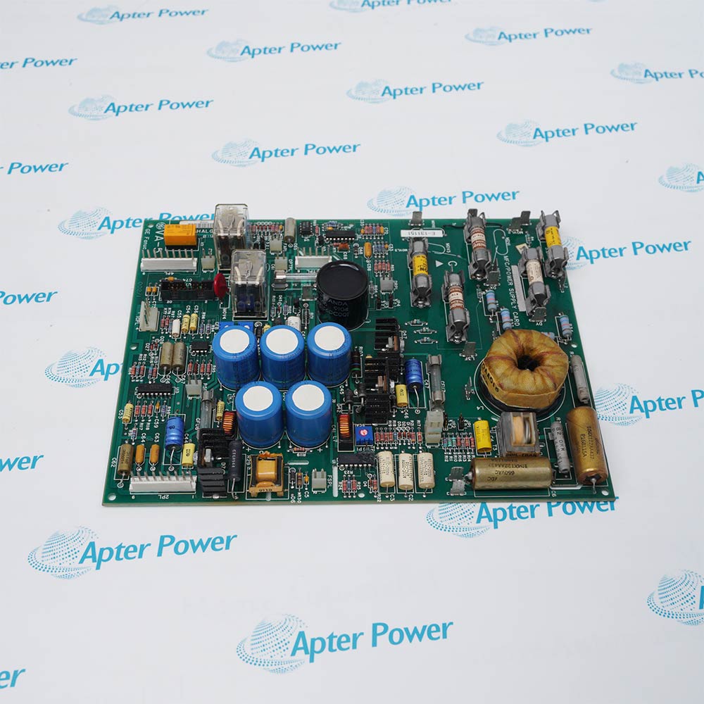
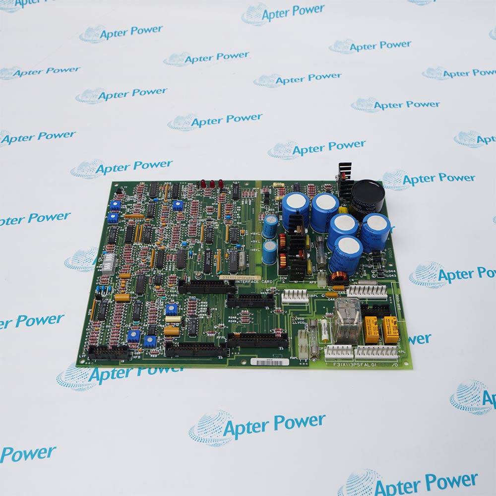
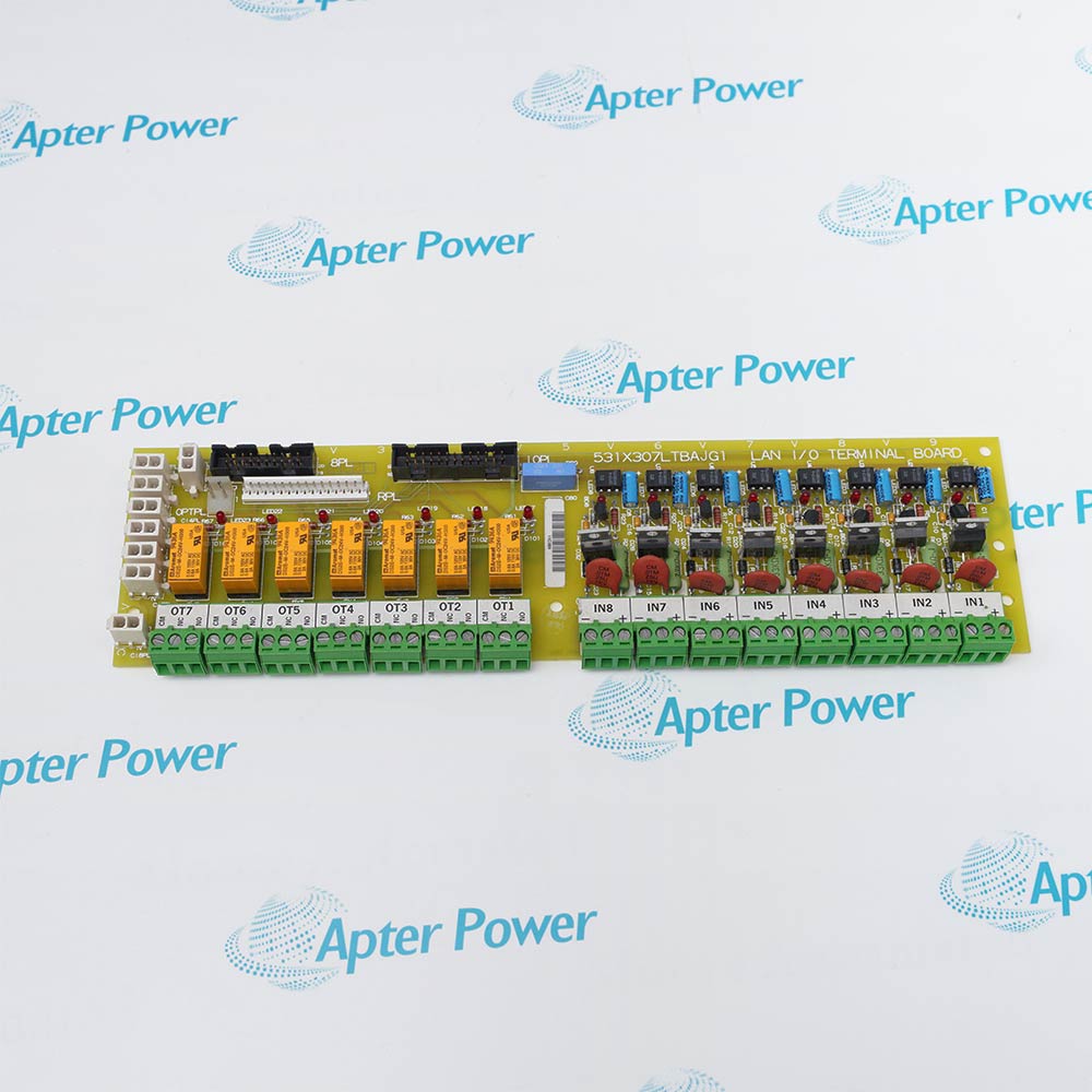
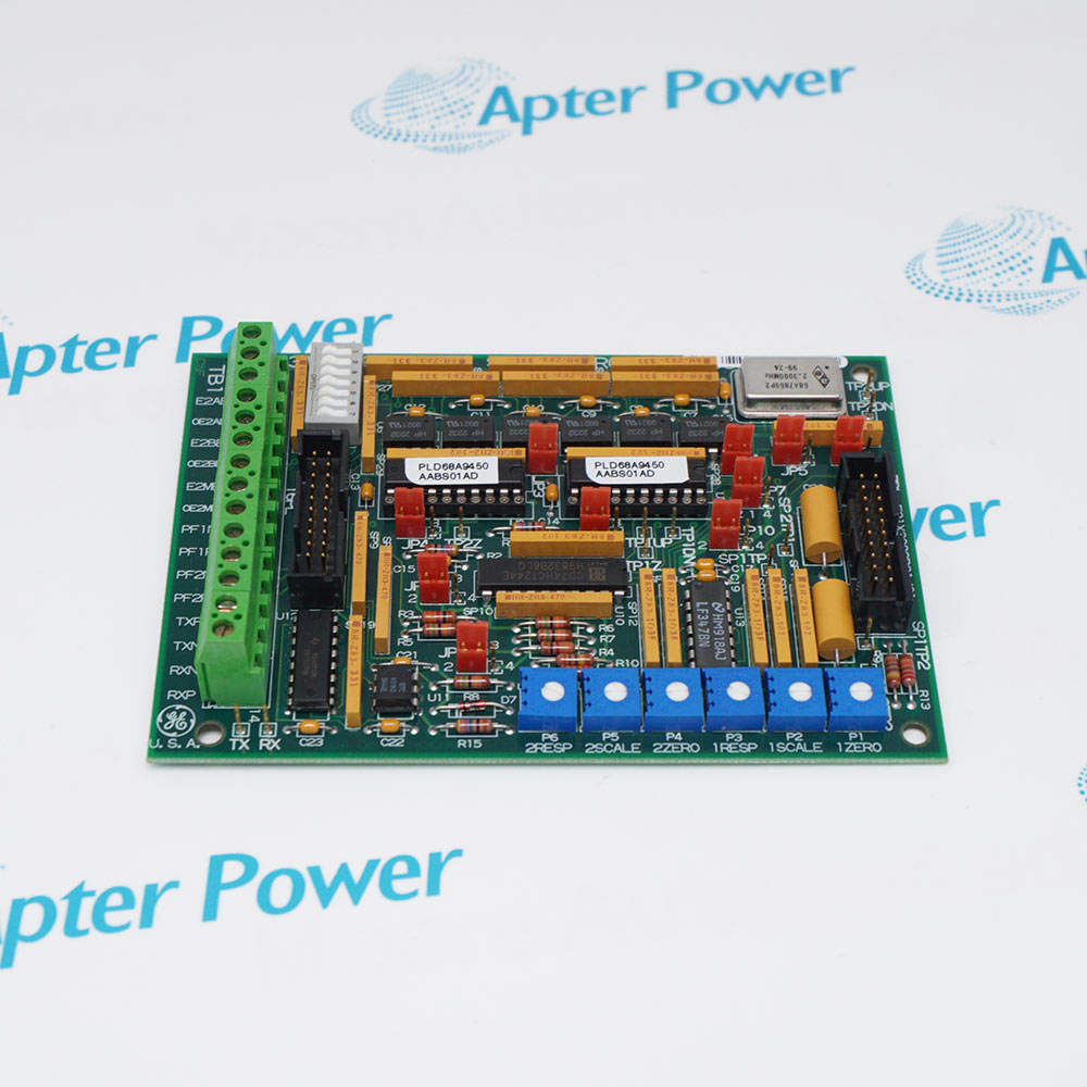
General Electric F31X139APMALG2FR00 is a Group 2 micro application board with five relays, twelve screw terminals, four potentiometers, and thirty-five integrated circuits.
In Stock
Ships by Saturday, November 14
Fast Shipping Available
Get a quick price for F31X139APMALG2FR00
Quantity
*E-mail
Company
*Mobile
*Content
Upload (gif, jpg, jpeg, png, bmp, doc, docx, xls, xlsx, ppt, pdf, csv)

Technical specifications for F31X139APMALG2FR00

  • Manufacturer:
    General Electric
  • Part Number:
    F31X139APMALG2FR00
  • Product Family:
    531X Drive Boards
  • Product Type:
    Micro Application Board
  • Stock:
    1
  • Series Group:
    Group 2
  • Board Function:
    Micro-application control
  • Requested Board Code:
    FR00
  • Drive Platform:
    DC-300
  • Terminal Strips:
    2
  • Terminal Positions:
    6 screw connections per strip
  • Relays:
    5
  • Jumpers:
    Approximately 20
  • Resistor Networks:
    More than 30
  • Potentiometers:
    4
  • Hardware Format:
    Printed circuit board
  • Tariff Code:
    8538900000
  • Country of origin:
    USA
  • Place of shipment:
    Xiamen, Fujian, China
By purchasing this item, you agree to the Terms & Conditions, ApterPower is not an authorized distributor for listed manufacturers or tradenames and therefore the manufacturer's warranty does not apply. All our products come with ApterPower's 1-year warranty.

More Information

Overview Manuals Relay Channels Terminal Map Logic Resources Application
  • APMAL Group 2 micro-application function
  • FR00 board-code execution
  • Terminal strips, relays, jumpers, resistor networks, and potentiometers support configurable drive logic

F31X139APMALG2FR00 is a General Electric Micro Application Board designed for GE DC-300 and compatible general-purpose drive systems.

It executes drive-specific micro-application logic and provides relay, jumper, adjustment, and terminal resources for the documented control configuration.

Before replacement, verify the full label, receiving position, connector keying, configuration hardware, paired assemblies, and every affected control or feedback path.

Availability, condition, price, and shipping time for F31X139APMALG2FR00 are confirmed during quotation.

General Electric F31X139APMALG2FR00 Micro Application Board Manuals, Product Family, Links

Important Notice: Other accessories, manuals, cables, calibration data, software, etc. are not included with this equipment unless listed in the above stock item description. All prices are shown in USD.

  • Five onboard relays provide switching resources for the installed micro-application logic
  • Each relay contact path is routed through the board's terminal and connector arrangement
  • Relay assignment depends on the DC-300 application drawing rather than the relay's physical position alone
  • Two terminal strips are mounted with their connection openings facing each other
  • Each strip provides six screw positions for a total of twelve field connection points
  • Terminal numbers, conductor tags, and relay associations should be captured as one wiring map
  • Thirty-five integrated circuits implement the board's application and interface logic
  • Approximately twenty jumpers and more than thirty resistor-network arrays establish the hardware configuration
  • Four potentiometers provide adjustable circuit points that must retain their FR00 settings
  • Custom application logic in GE DC-300 drives
  • Relay and terminal interfacing in related GE general-purpose drives
  • Process-specific motor-control sequences using the APMAL Group 2 board
Description
F31X139APMALG2FR00 is the FR00 execution of a Group 2 micro application board for the GE DC-300 and related general-purpose drives. Its application circuitry is built around thirty-five integrated circuits and five onboard relays.

Two terminal strips are positioned with their openings facing each other. Each strip contains six screw connections, giving the board twelve terminal points for the relay and application circuits assigned by the drive wiring design.

Approximately twenty jumpers, more than thirty resistor-network arrays, and four potentiometers establish the configurable hardware arrangement. Four vertical pin headers and two vertical cable connectors link this logic and terminal section with the surrounding drive boards.
Alternative Names
F31X139APMALG2FR00 GE F31X139APMALG2FR00 General Electric F31X139APMALG2FR00 GE DC-300 F31X139APMALG2FR00 F31X 139 APMAL G2FR00 F31X-139-APMAL-G2FR00 531X139APMALG2FR00
Technical notes
F31X139APMALG2FR00 places two six-position terminal strips opposite one another; its five relay paths must follow the installed terminal map.
Exceptional Service

Our Mission

  • 100% Satisfaction

    We believe expertise is priceless. With over 20 years of experience, and top engineers on staff, we can help you solve or avoid problems that threaten your business.
  • Trust Guaranteed

    Not only do we have a vast inventory, our team makes sure every piece of equipment is in working condition. Your purchases are also backed by our Warranty.
  • Expertise

    Time is money, especially when your equipment is down. We work quickly to get your equipment on its way so you can get it back up and running.

FAQS

The following is a list of questions commonly asked by our customers. Please contact us if you have a question about our process that is not answered below.
What control role does General Electric F31X139APMALG2FR00 perform?
It provides Group 2 micro-application logic for DC-300 and related general-purpose drive configurations.
How are the terminal strips arranged on General Electric F31X139APMALG2FR00?
Two strips face one another, and each strip provides six screw positions for a total of twelve terminal connections.
How many relays are installed on General Electric F31X139APMALG2FR00?
Five relays are installed for application-dependent switching through the board's terminal and connector circuits.
Which configurable components are fitted to General Electric F31X139APMALG2FR00?
The board contains approximately twenty jumpers, more than thirty resistor-network arrays, and four potentiometers.
Which board connectors are present on General Electric F31X139APMALG2FR00?
It has four vertical pin-header connectors and two vertical pin cable connectors for interfaces with surrounding drive hardware.
How many integrated circuits are used by General Electric F31X139APMALG2FR00?
Thirty-five integrated circuits are recorded across the board's application and interface logic sections.
What should be checked when a relay output from General Electric F31X139APMALG2FR00 is inactive?
Trace the assigned screw terminal, relay contact path, cable connector, jumper pattern, potentiometer setting, and the command produced by the application logic.