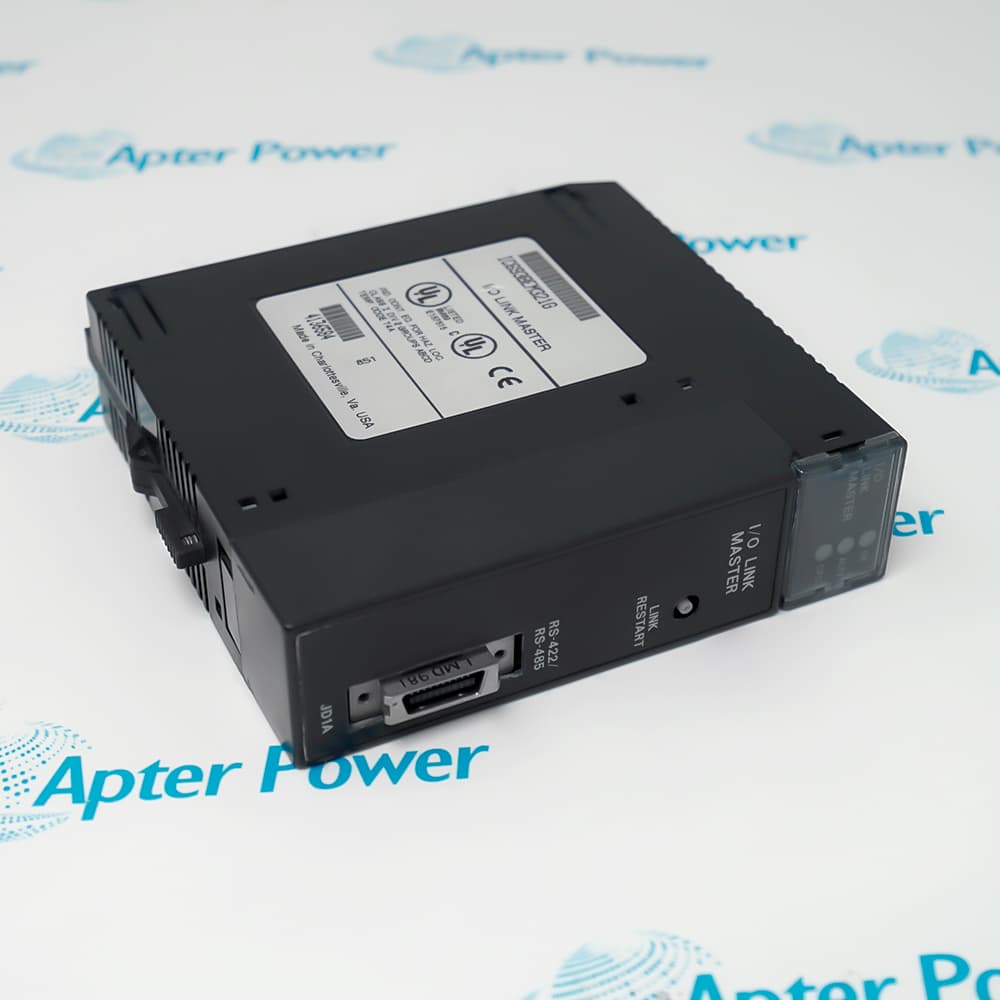
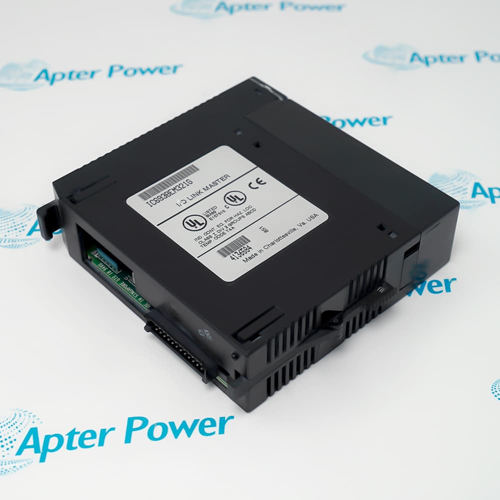
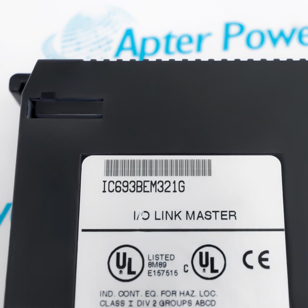
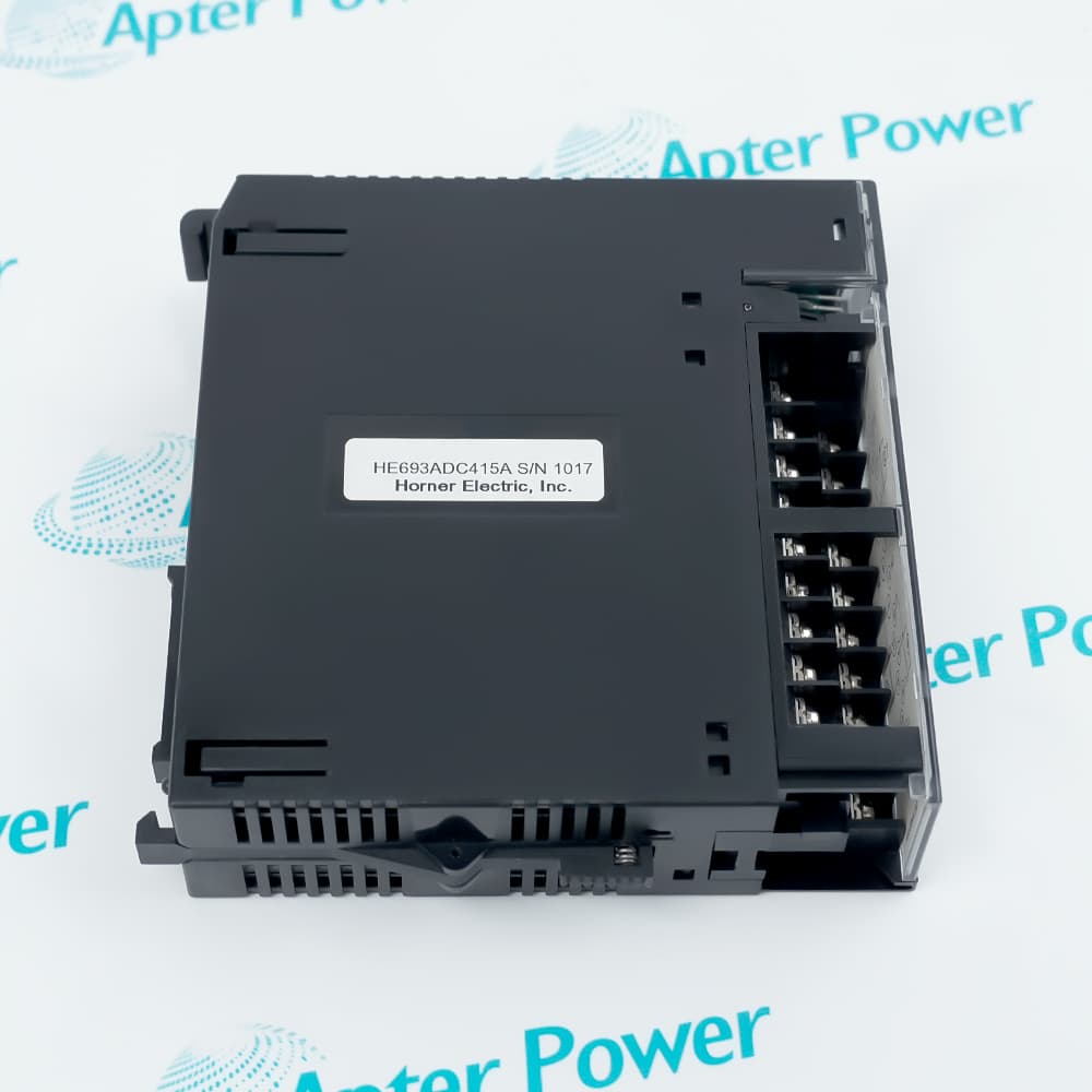
Features:
- High-speed proprietary Fanuc I/O Link master for up to 16 slave devices
- Capacity for 1024 discrete inputs and 1024 discrete outputs
- Electrical or optical network segments supported through the appropriate adapter
IC693BEM321 operates with supported Series 90-30 CPUs from release 4.4 and can be configured with a Hand-held Programmer or Logicmaster 90-30 Configurator release 4.5 or later.
The module may occupy any Series 90-30 slot except the CPU position. GE Fanuc recommends the CPU rack or an expansion rack when available, while installation in a remote rack requires an electrical link connection.
Documented slave choices include compatible Power Mate models, Series 0 CNC equipment, Fanuc operator and connection units, and Series 90 PLCs operating as universal I/O Link slaves.
Apter Power can assist with sourcing and official documentation for the General Electric IC693BEM321 Series 90-30 I/O Link Master Module after manufacturer End-of-Life (EOL).
General Electric IC693BEM321 I/O Link Master Module Manuals, Datasheets, Links
Important Notice: Other accessories, manuals, cables, calibration data, software, etc. are not included with this equipment unless listed in the above stock item description. All prices are shown in USD.
General Electric IC693BEM321 I/O Link Master Module Specs
General
- ManufacturerGeneral Electric
- ModelIC693BEM321
- ConditionNew Original ready stock
- Product FamilyGE 90-30 Series PLC
Important Notice: Other accessories, manuals, cables, calibration data, software, etc. are not included with this equipment unless listed in the above stock item description. All prices are shown in USD.
Network planning
- Topology: Arrange each slave in the configured sequence so the controller can map link data without gaps.
- Node limit: Keep the completed segment within the documented maximum of 16 slave devices.
- Cabling: Use the specified shielded twisted-pair cable and terminate the selected link medium at both ends.
- Segment length: Keep each electrical run within the maximum distance specified for the selected transfer rate.
Controller data allocation
- Input references: Assign incoming link data to %I or %AI memory according to the controller program structure.
- Output references: Place outgoing data in %Q, %AQ, %G, or %R memory as supported by the configuration.
- Status word: Reserve the module status word so the application can identify ready, operating, and error states.
- Failure response: Select data defaulting or last-state retention to define how output data behaves after communication is lost.
Link restoration procedure
- Fault correction: Repair cabling, power, or slave-device conditions before attempting to restart communication.
- Slave readiness: Confirm every intended slave is online, because restart can otherwise establish only a partial link.
- One-shot command: Pulse restart or reset for one PLC scan instead of maintaining the command continuously.
- Post-restart check: Review module status and mapped input data to verify that the complete configured link has returned.