Features:
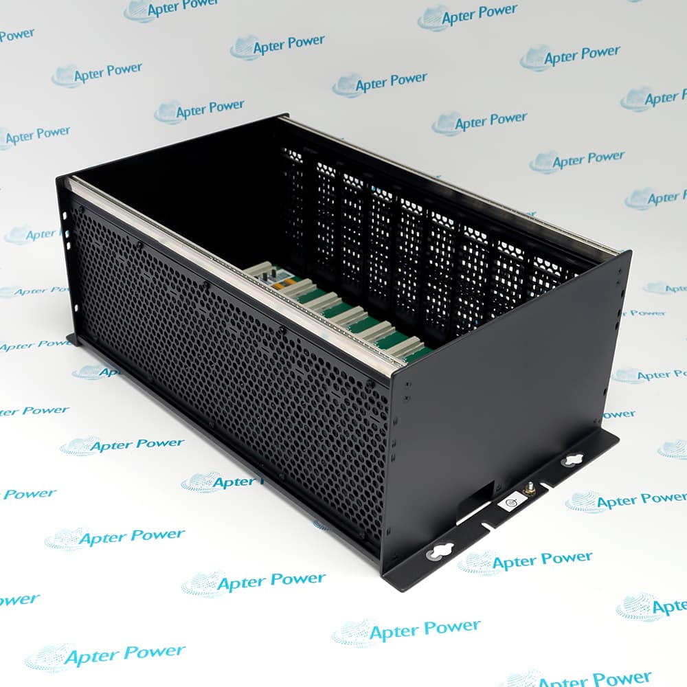
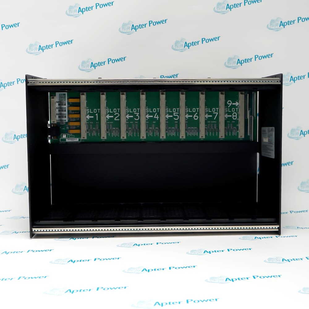
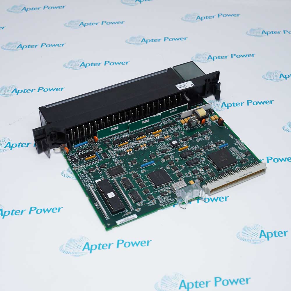
- Provides nine IC697 module positions beside a dedicated power-supply position.
- Senses rack and slot location through the backplane instead of module address switches.
- Allows one suitably rated IC697 supply to feed a second rack through IC697CBL700.
The steel chassis is fixed to the rear panel before the power supply and control modules are seated in their assigned positions.
Backplane sensing presents each inserted module with the rack-and-slot identity used by Series 90-70 configuration software.
Natural convection normally cools the assembly when enclosure depth, clearances and installed-module loading remain within the rack limits.
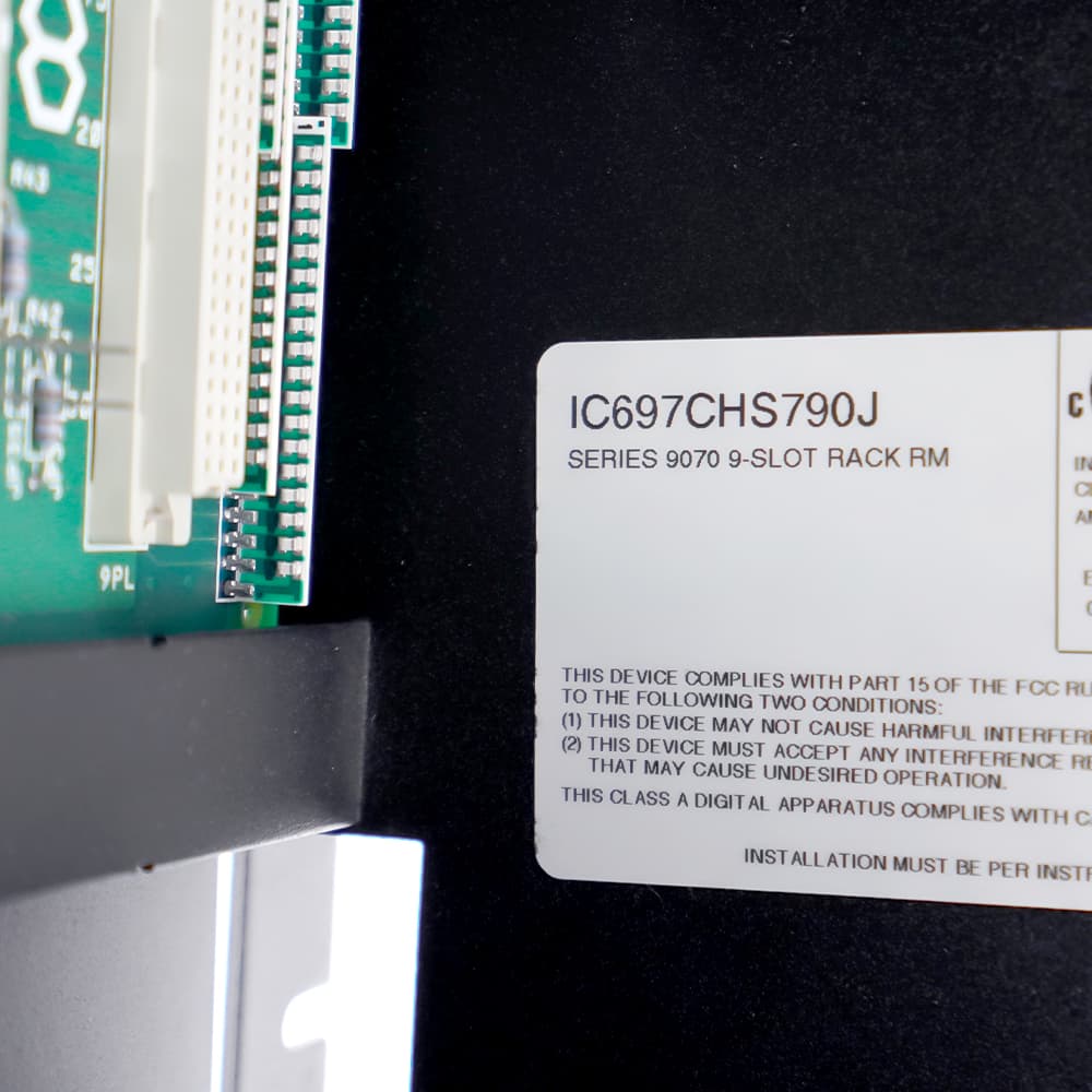
The General Electric IC697CHS790 Series 90-70 PLC Rack may still be available for purchase and support from Apter Power beyond End-Of-Life (EOL) by the manufacturer (OEM).
General Electric IC697CHS790 Series 90-70 PLC Rack Manuals,Datasheets,Link
Important Notice: Other accessories, manuals, cables, calibration data, software, etc. are not included with this equipment unless listed in the above stock item description. All prices are shown in USD.
How the backplane locates modules
- Physical position: Nine keyed module connectors establish the usable positions to the right of the power supply.
- Location sensing: Backplane signals identify the rack and slot occupied by each installed IC697 module.
- I/O reference: The controller derives module addressing from position rather than from local DIP switches.
- Configuration check: Configured slot assignments must agree with the hardware installed in the corresponding connector.
Setting the chassis number
- Jumper location: Four identification jumpers are placed behind the power-supply position.
- Binary weights: The links represent values 1, 2, 4 and 8 for the rack-number selection.
- Power-off access: Remove power before exposing or changing the jumpers behind the supply.
- Project match: The physical jumper total must match the rack number defined in the PLC configuration.
Supplying a second chassis
- Source position: The installed IC697 supply powers the local backplane from the dedicated left position.
- Link cable: IC697CBL700 carries the supply connection from the source rack to one additional rack.
- Load calculation: Add the 5 V demand of both racks before choosing the supply rating.
- Current range: Available bus capacity depends on whether the selected supply provides 11 A, 18 A or 20 A at 5 V.
Enclosure and airflow planning
- Rear mounting: The rack bolts to a flat rear panel inside a 254 mm-deep enclosure.
- Convection path: Leave free air space around the chassis so heat can rise past installed modules.
- Fan decision: Forced air is not normally needed unless enclosure temperature or module loading requires it.
- Service clearance: Keep front access available for power-supply, CPU and I/O module removal.