Ask our team:
  • Phone: +86 181 0690 9650
  • E-Mail sales1@apterpower.com
  • Lifecycle status

    Discontinued / Obsolete by OEM
    Apter Power supports IC697BEM713 availability and quotation enquiries for installed Series 90-70 systems.

IC697BEM713

/ 4.9
1001 reviews | Need a Specific Revision?
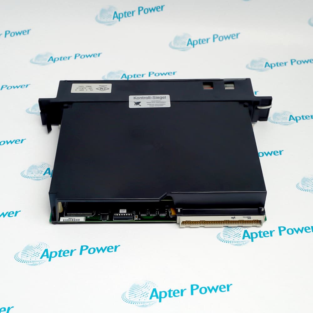
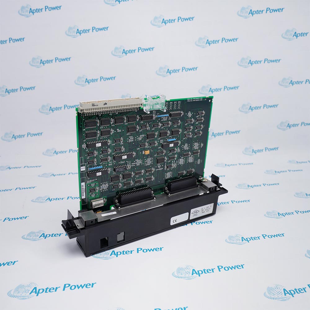
General Electric IC697BEM713 is a Bus Transmitter Module that starts the Series 90-70 parallel expansion bus from the CPU rack.
In Stock
Ships by Wednesday, October 28
Fast Shipping Available
Get a quick price for IC697BEM713
Quantity
*E-mail
Company
*Mobile
*Content
Upload (gif, jpg, jpeg, png, bmp, doc, docx, xls, xlsx, ppt, pdf, csv)

Technical specifications for IC697BEM713

  • Manufacturer:
    General Electric
  • Part Number:
    IC697BEM713
  • Product Family:
    GE 90-70 Series PLC
  • Product Type:
    Bus Transmitter Module
  • Stock:
    1
  • Interfaces:
    Parallel programmer and bus expansion
  • Expansion capacity:
    Up to seven expansion racks
  • Maximum cable length:
    15 m (50 ft) total
  • Rack position:
    Main CPU rack; not slot 1
  • Status indicators:
    Module, programmer port, and expansion port
  • Tariff Code:
    8538900000
  • Country of origin:
    USA
  • Place of shipment:
    Xiamen,Fujian,China
By purchasing this item, you agree to the Terms & Conditions, ApterPower is not an authorized distributor for listed manufacturers or tradenames and therefore the manufacturer's warranty does not apply. All our products come with ApterPower's 1-year warranty.

More Information

Overview Manuals CPU Rack Fit Parallel Interfaces Port Indicators Configuration

Features:

  • CPU-rack bus interface.
  • Parallel programmer connector.
  • Up to seven expansion racks.
CPU-rack bus interface establishes the principal capability of IC697BEM713 within its Series 90-70 function.

The relationship between parallel programmer connector and up to seven expansion racks determines how the module fits the surrounding rack, network, or field circuit.

During service, 50 ft total inter-rack cable must remain consistent with the saved application and the installed hardware.

Apter Power supports availability and quotation enquiries for General Electric IC697BEM713 Bus Transmitter Module.
General Electric IC697BEM713 Bus Transmitter Module Manuals, Datasheets, Links Important Notice: Other accessories, manuals, cables, calibration data, software, etc. are not included with this equipment unless listed in the above stock item description. All prices are shown in USD.

Transmitter placement in the main rack

  • Rack location: IC697BEM713 belongs in the main CPU rack and may use any open slot except slot 1.
  • Receiver pairing: Its expansion port feeds IC697BEM711 receivers installed at the head of each expansion rack.
  • Rack reach: A single transmitter can extend the system to seven additional IC697 racks.
  • Version condition: Version IC697BEM713A is positioned to the right of an IC697BEM731 when both modules are present.

Two distinct ports on IC697BEM713

  • Programmer port: The upper connector provides the high-performance parallel path for the programming device.
  • Expansion port: The lower connector launches the daisy-chained parallel bus toward the receiver modules.
  • Cable boundary: The total path from the transmitter to the final receiver is limited to 15 m (50 ft).
  • Port separation: Programmer traffic and rack expansion use different physical connectors on the module.

Reading transmitter activity

  • Module LED: OK reports the operating state of IC697BEM713 itself.
  • Programming activity: PGMR ACTIVE changes with traffic on the parallel programmer interface.
  • Expansion activity: BUS ACTIVE identifies communication on the rack-expansion path.
  • Troubleshooting order: The three indications separate a module problem from programmer-port or expansion-bus inactivity.

Bringing the bus transmitter online

  • Power isolation: The CPU rack is de-energized before the module or either parallel cable is moved.
  • Physical check: Both connectors are seated and strain-relieved according to their programmer and expansion roles.
  • Software entry: IC697BEM713 is added to the Series 90-70 hardware configuration without DIP-switch settings.
  • Startup result: Normal port indications are confirmed before relying on any attached expansion rack.
Description
General Electric IC697BEM713 is a Bus Transmitter Module for the Series 90-70 platform, where it starts the Series 90-70 parallel expansion bus from the CPU rack.

Its design combines CPU-rack bus interface with parallel programmer connector, giving the installed unit a clearly defined operating role.

up to seven expansion racks and 50 ft total inter-rack cable govern the way this model is integrated, commissioned, and matched during replacement.
Revisions

Revision Part #

Also known as

IC697BEM713G
IC697BEM713-G, Series G, Rev G
IC697BEM713F
IC697BEM713-F, Series F, Rev F
IC697BEM713E
IC697BEM713-E, Series E, Rev E
IC697BEM713D
IC697BEM713-D, Series D, Rev D
IC697BEM713C
IC697BEM713-C, Series C, Rev C
IC697BEM713B
IC697BEM713-B, Series B, Rev B
IC697BEM713A
IC697BEM713-A, Series A, Rev A
Alternative Names
General Electric IC697BEM713 GE Fanuc IC697BEM713 GE IC697BEM713 IC697 BEM713 IC697-BEM713 Series 90-70 IC697BEM713 IC697BEM7I3 IC 697 BEM713
Technical notes
IC697BEM713 service records should preserve up to seven expansion racks and 50 ft total inter-rack cable so the replacement matches the operating Series 90-70 configuration.
Exceptional Service

Our Mission

  • 100% Satisfaction

    We believe expertise is priceless. With over 20 years of experience, and top engineers on staff, we can help you solve or avoid problems that threaten your business.
  • Trust Guaranteed

    Not only do we have a vast inventory, our team makes sure every piece of equipment is in working condition. Your purchases are also backed by our Warranty.
  • Expertise

    Time is money, especially when your equipment is down. We work quickly to get your equipment on its way so you can get it back up and running.

FAQS

The following is a list of questions commonly asked by our customers. Please contact us if you have a question about our process that is not answered below.
Which system detail must match before installing IC697BEM713?
For IC697BEM713, confirm the complete model, Series 90-70 role, CPU-rack bus interface, and parallel programmer connector before installation.
How should a startup fault on IC697BEM713 be isolated?
Check IC697BEM713 rack power, seating, configuration, indicators, and up to seven expansion racks before deciding that the module has failed.
What should be recorded before replacing IC697BEM713?
Record the IC697BEM713 slot, connections, settings, hardware suffix, parallel programmer connector, and 50 ft total inter-rack cable before removing power.
How is IC697BEM713 checked after commissioning?
Confirm normal IC697BEM713 indications, clear faults, exercise the intended function, and compare the result with the saved control state.
Can a neighboring Series 90-70 model replace IC697BEM713 without review?
A neighboring module may differ in CPU-rack bus interface, parallel programmer connector, or up to seven expansion racks; verify the complete IC697BEM713 identity and configuration first.
What external condition can affect IC697BEM713 operation?
For IC697BEM713, inspect the connected rack, field circuit, communication path, or power path associated with parallel programmer connector.
When should IC697BEM713 be returned to service?
Return IC697BEM713 only after configuration, connections, diagnostics, and the 50 ft total inter-rack cable requirement have been verified under a controlled test.

Product Browsing History