Features:
- Signal Gateway Between Field Input Sources and the Mark V Control System Cores
- Enables Simultaneous Handling of Vibration, Voltage, Pulse Rate, and Stall Detection Signals with Cross-Core Connectivity
- Functions in Coordination with the TCQA and TCQC Boards Across R2 and R3 Core Configurations
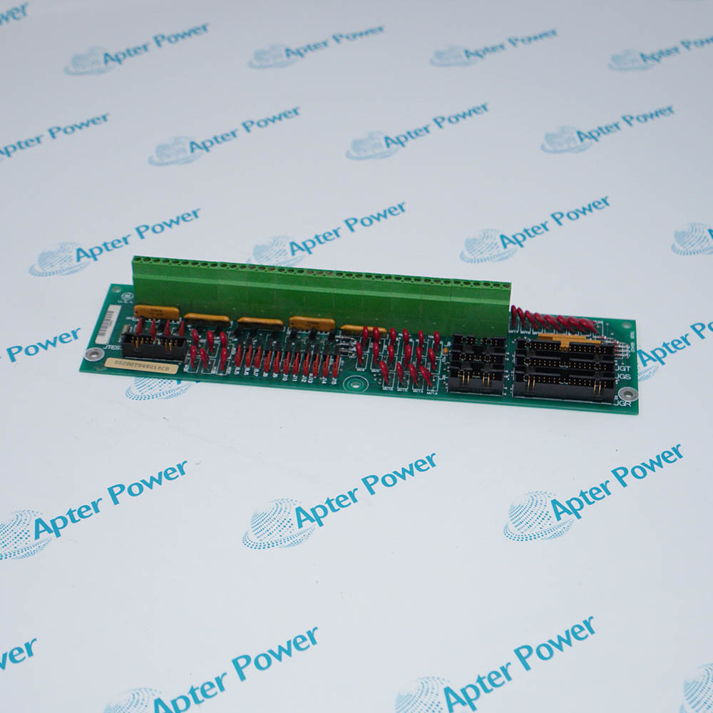
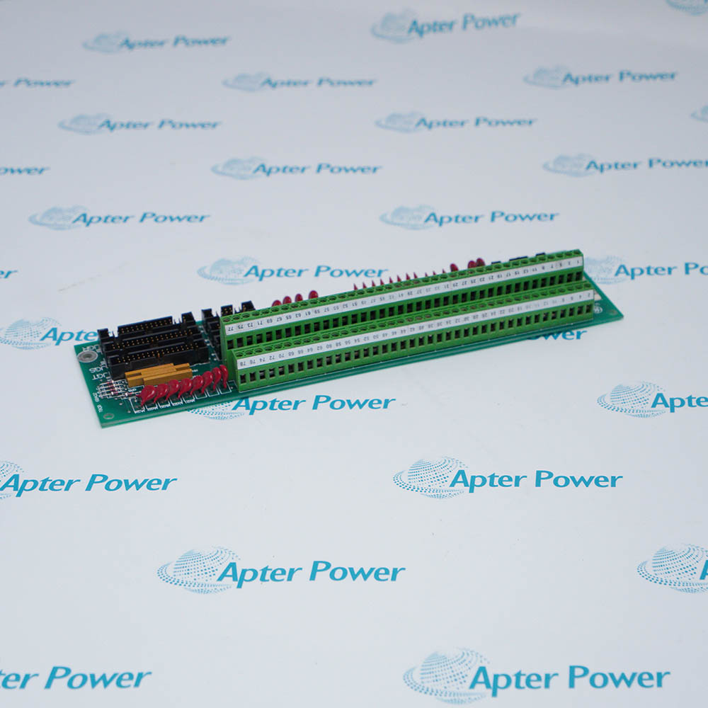
The General Electric DS200TBQBG1ACB Input Termination Module serves as the critical signal interface within the Mark V control system, bridging multiple input sources and the core processing boards. The DS200TBQBG1ACB consolidates the capability of receiving diverse signal types—voltage, vibration, pulse rate, and compressor stall detection—while providing structured connectivity support across redundant system cores.
The DS200TBQBG1ACB provides essential input termination functions common to the entire control system, and is a critical component of the monitoring path, directly affecting the proper, normal operation of the overall turbine or generator control system. One DS200TBQBG1ACB module is required per core (R2 and R3) depending on the desired monitoring coverage. The DS200TBQBG1ACB occupies a dedicated position within the core and is always located at position seven, serving as the central hub for all input signal management within that specific core.
For comprehensive dual-core monitoring applications, the Mark V system requires a DS200TBQBG1ACB module installed in both the R2 and R3 cores. In addition to standard single-core signal handling, this distributed configuration also performs coordinated signal transfer. The DS200TBQBG1ACB dual-core configuration executes signal routing using the internal JGR and JHR connections specified in the termination board design. Using this method, the DS200TBQBG1ACB system continually monitors the integrity of all incoming signals. If the system detects that a particular signal path is no longer providing stable data (outside configured tolerance levels or experiencing connection faults), it will automatically reroute critical monitoring information through alternative pathways and flag the event for system diagnostics.
The DS200TBQBG1ACB General Electric Input Termination Module may still be available for purchase and support from Apter Power beyond End-Of-Life (EOL) by the manufacturer (OEM).
General Electric DS200TBQBG1ACB Input Termination Module Manuals,Datasheets,Link
Important Notice: Other accessories, manuals, cables, calibration data, software, etc. are not included with this equipment unless listed in the above stock item description. All prices are shown in USD.
General Electric DS200TBQBG1ACB Input Termination Module Specs
General
- Manufacturer General Electric
- Model DS200TBQBG1ACB
- Condition New Original ready stock
- Product Family DS200TBQBG1A,DS200TBQBG1ABB,DS200TBQBG1AAB
Important Notice: Other accessories, manuals, cables, calibration data, software, etc. are not included with this equipment unless listed in the above stock item description. All prices are shown in USD.
- Signal Handling: Processes vibration signals, analog voltage, and pulse frequency (speed) signals.
- System Placement: Typically installed in position 7 of the R2 and R3 cores within the Mark V cabinet.
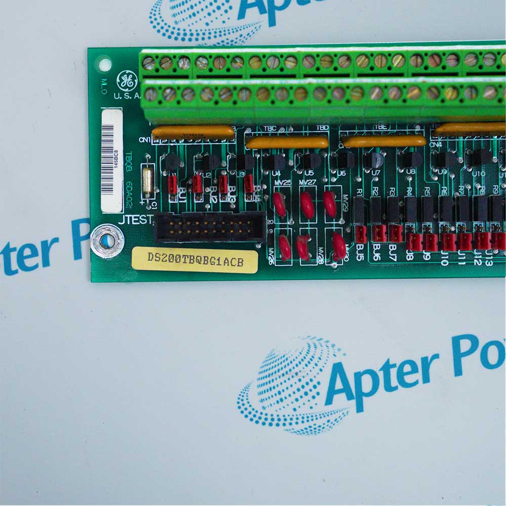
- Vibration/Analog: Routed via the JGR connector to the TCQA board.
- Pulse/Stall Detection: Routed via the JHR connector to the TCQC board.
- Jumper Settings (BJ1–BJ4): Used to configure signal splitting for pressure sensors, specifically for compressor stall detection.
- Load Resistor Configuration (BJ5–BJ7): Used to convert voltage inputs into mA signals for specific sensor requirements.
- I/O Terminals: Features two large terminal blocks (74 terminals total) for direct field wiring.
- No Onboard Firmware: As a passive termination board, this module does not contain a microprocessor or programmable firmware.
- System Compatibility: Updates are handled at the controller level (the "R" core).
- Wiring: Recommend using three-conductor shielded triad cable for field wiring between the Proximitor® Sensor and the monitor, with a maximum distance of 305 meters (1,000 feet).
- Revision Codes: The "ACB" suffix represents the specific hardware revision. When replacing the unit, ensuring the revision matches is critical to maintain compatibility.

 The GE Mark VIe Distributed I/O is an Ethernet-distributed, hot-swappable I/O subsystem purpose-built for Mark VIe turbine and plant control.