Ask our team:
  • Phone: +86 181 0690 9650
  • E-Mail sales1@apterpower.com
  • Lifecycle status

    Active / Available from OEM
    Apter Power supports DS200PCCAG8A revision review, quotation coordination and sourcing enquiries.

DS200PCCAG8A

/ 4.9
1001 reviews | Need a Specific Revision?
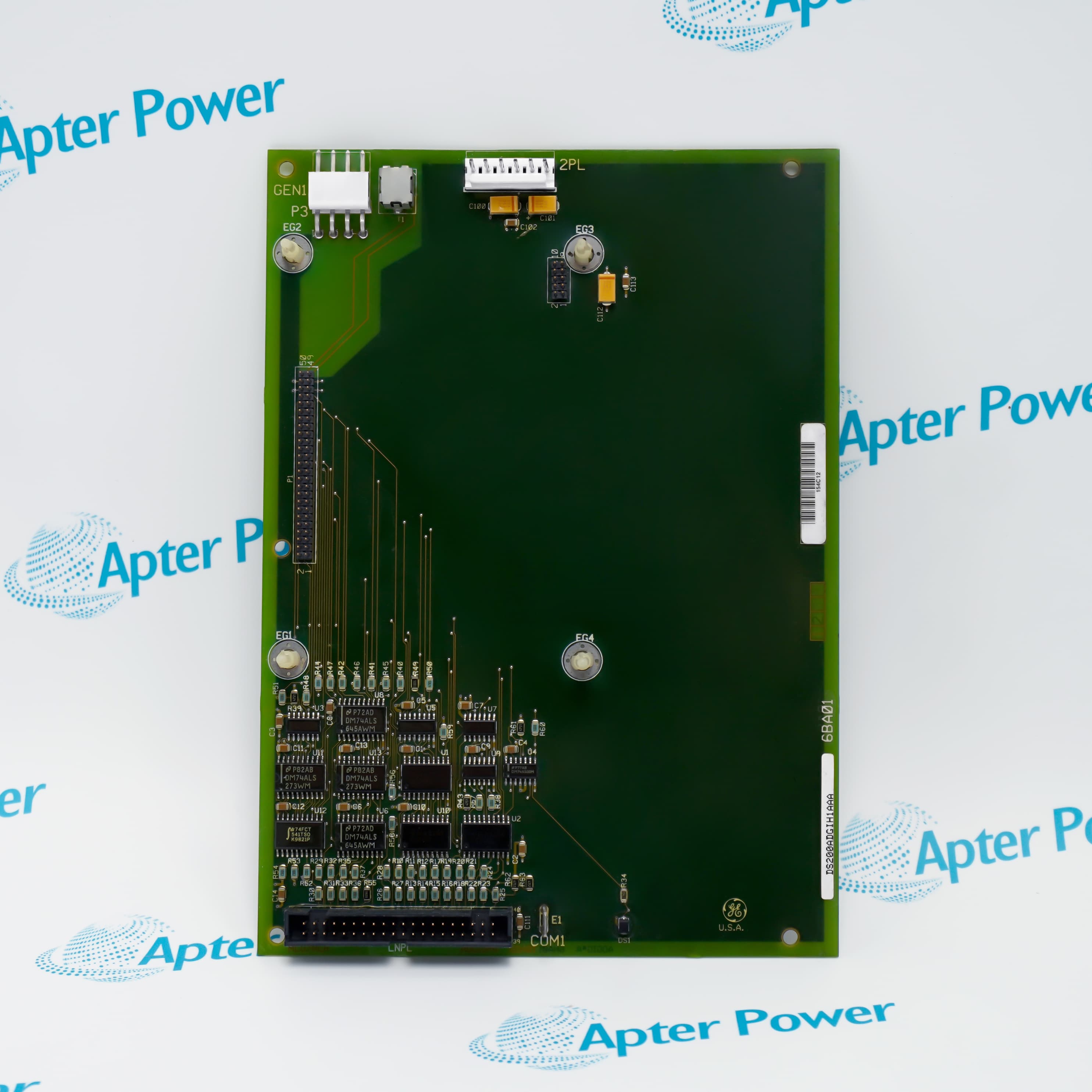
General Electric DS200PCCAG8A is a G8 non-regenerative PCCA power connect card that links SDCI control circuitry to an SCR bridge with AC/DC snubbers and 240–700 V armature scaling.
In Stock
Ships by Friday, October 30
Fast Shipping Available
Get a quick price for DS200PCCAG8A
Quantity
*E-mail
Company
*Mobile
*Content
Upload (gif, jpg, jpeg, png, bmp, doc, docx, xls, xlsx, ppt, pdf, csv)

Technical specifications for DS200PCCAG8A

  • Manufacturer:
    General Electric
  • Part Number:
    DS200PCCAG8A
  • Product Family:
    GE Mark V/VI Driver Board
  • Product Type:
    DC2000 Power Connect Card
  • Stock:
    1
  • Board Function:
    PCCA power connection
  • Board Group:
    G8
  • Control Platform:
    DC2000
  • Bridge Application:
    Non-regenerative
  • Power-Supply Interface:
    SDCI board
  • AC Input Limit:
    Up to 600 V rms
  • Armature Scaling:
    240 to 700 V
  • Snubber Networks:
    AC and DC
  • Weight:
    0.72 kg
  • Estimated shipping dimensions:
    27.8x21.2x2.5cm
  • Tariff Code:
    8537101190
  • Country of origin:
    USA
  • Place of shipment:
    Xiamen, Fujian, China
By purchasing this item, you agree to the Terms & Conditions, ApterPower is not an authorized distributor for listed manufacturers or tradenames and therefore the manufacturer's warranty does not apply. All our products come with ApterPower's 1-year warranty.

More Information

Overview Manuals Bridge Interface Voltage Scaling Snubber and Supply Product Applications

Features:

  • Group-G8 non-regenerative interface between DC2000 control circuitry and an SCR power bridge.
  • 240–700 V armature scaling with an associated AC-line limit of 600 V rms.
  • AC/DC snubber networks with JP1, JP2, WP3 and WP4 configuration links.
DS200PCCAG8A uses the SDCI control-side arrangement documented for C-frame and G-frame drive assemblies.

JP1 and JP2 select the voltage-scaling connection, while WP3 and WP4 define the snubber and voltage-feedback relationship.

The G8 identity preserves the non-regenerative bridge boundary and must remain distinct from regenerative PCCA groups.

Apter Power supports official-document review, quotation coordination and sourcing enquiries for the General Electric DS200PCCAG8A DC2000 Power Connect Card.
General Electric DS200PCCAG8A DC2000 Power Connect Card Manuals,Datasheets,Link Important Notice: Other accessories, manuals, cables, calibration data, software, etc. are not included with this equipment unless listed in the above stock item description. All prices are shown in USD.
  • The PCCA forms the isolated interface between DC2000 control circuitry and the SCR power bridge.
  • Group G8 is the non-regenerative PCCA selection; it is not the regenerative G7 path.
  • The SDCI-side firing-control circuit supplies the control interface used by the G8 arrangement.
  • Bridge gate paths route firing commands to the six SCR positions in the forward power bridge.
  • Group G8 is documented for non-regenerative armature-voltage scaling from 240 to 700 V.
  • The G7/G8 application table limits the associated AC line input to 600 V rms.
  • JP1 and JP2 connect to the specified P3–P10 stabs according to group number and system voltage.
  • Confirm the installed voltage and jumper map before transferring wiring to DS200PCCAG8A.
  • The G8 configuration uses both AC-side and DC-side snubber networks.
  • The documented G7/G8 arrangement applies to C-frame and G-frame drives with an SDCI supply board.
  • Line fuses and line reactors form part of the supported power path around the PCCA.
  • The bus transformer may be common or separate, so the installed topology must be retained during replacement.
  • DC2000 non-regenerative drive systems that use a group-G8 PCCA power-bridge interface.
  • C-frame and G-frame power-conversion assemblies using the documented SDCI control arrangement.
  • SCR bridge applications requiring isolated firing-command transfer and AC/DC transient suppression.
  • Revision-managed maintenance where the complete installed suffix and jumper layout are preserved.
Description
DS200PCCAG8A is a General Electric group-eight PCCA power connect card forming the isolated interface between DC2000 control circuitry and a non-regenerative SCR power bridge. Its G8 arrangement works with an SDCI supply board in C-frame or G-frame drive assemblies.

DS200PCCAG8A uses JP1 and JP2 to select the armature-voltage scaling connection for the installed group and system voltage. WP3 and WP4 preserve the snubber-capacitor and voltage-feedback relationship, helping maintenance teams restore the original power-path configuration.

For DS200PCCAG8A replacement work, retain the G8 identity, installed jumper map, line fuses and reactors, and common or separate bus-transformer topology. These boundaries distinguish the non-regenerative G8 assembly from regenerative PCCA groups that may appear visually similar.
Revisions

Revision Part #

Also known as

DS200PCCAG8ACB
DS200PCCAG8A-CB, Series -CB, Rev -CB
Alternative Names
GE DS200PCCAG8A General Electric DS200PCCAG8A DS200-PCCA-G8A DS200 PCCA G8A GE PCCA G8 Power Connect Card General Electric Group 8 PCCA Board DS200PCCAG8-A
Technical notes
DS200PCCAG8A is the G8 non-regenerative PCCA arrangement for 240–700 V armature scaling with an SDCI supply interface and AC/DC snubbers. A G7 or G9 board belongs to a regenerative group and changes the bridge application boundary; replacement review must therefore preserve the G8 group, jumper configuration, and installed power-bridge wiring.
Exceptional Service

Our Mission

  • 100% Satisfaction

    We believe expertise is priceless. With over 20 years of experience, and top engineers on staff, we can help you solve or avoid problems that threaten your business.
  • Trust Guaranteed

    Not only do we have a vast inventory, our team makes sure every piece of equipment is in working condition. Your purchases are also backed by our Warranty.
  • Expertise

    Time is money, especially when your equipment is down. We work quickly to get your equipment on its way so you can get it back up and running.

FAQS

The following is a list of questions commonly asked by our customers. Please contact us if you have a question about our process that is not answered below.
What installed-drive details should be sent with an RFQ for DS200PCCAG8A?
Send the complete installed suffix, drive frame, G8 group, DC2000 control arrangement and existing jumper map. These details allow the quotation to be checked against the installed non-regenerative bridge instead of a visually similar PCCA card.
Can DS200PCCAG8A be selected for both C-frame and G-frame DC2000 assemblies?
Yes, but only where the installed drive uses the SDCI-based group-G8 non-regenerative arrangement. Stop the selection if the drive documentation identifies a regenerative PCCA group or a different supply interface.
What should a commissioning engineer compare after installing DS200PCCAG8A?
Compare the restored JP1/JP2 and WP3/WP4 positions with the removed-board record before energizing. A mismatch changes the intended voltage-scaling, snubber or feedback connection, so commissioning should stop until the map agrees.
Where should troubleshooting begin if DS200PCCAG8A receives control commands but the SCR bridge does not respond?
Start at the boundary between the SDCI control interface and the six forward-bridge gate paths. Confirm the command reaches the board, then check the corresponding gate-path connection; a control-side signal alone does not prove bridge-side transfer.
Why must the bus-transformer arrangement be identified before replacing DS200PCCAG8A?
The group-G8 power path may use a common or separate bus transformer. Match that topology and the surrounding line-fuse and reactor arrangement before wiring transfer; stop if the installed path cannot be established.
How should the DS200PCCAG8ACB revision be quoted for an installed DS200PCCAG8A?
Quote the complete DS200PCCAG8ACB code and retain the installed suffix and jumper record. The revision entry does not remove the need to match the group-G8 non-regenerative configuration before supply.
What evidence should be retained before removing DS200PCCAG8A from a legacy DC2000 drive?
Photograph the full board suffix, connector locations, jumper and wire-link positions, and surrounding power-path labels before disconnection. Keep those records with the maintenance job so the replacement can be reviewed without relying on memory or board appearance.