Features:
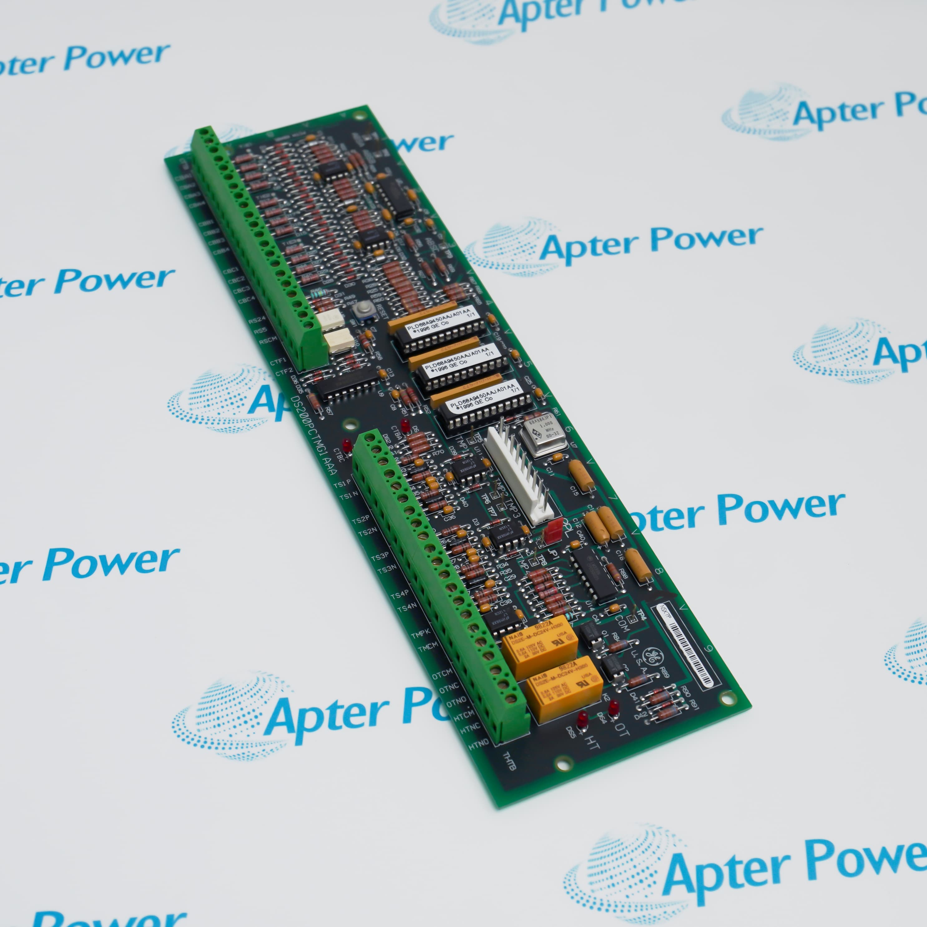
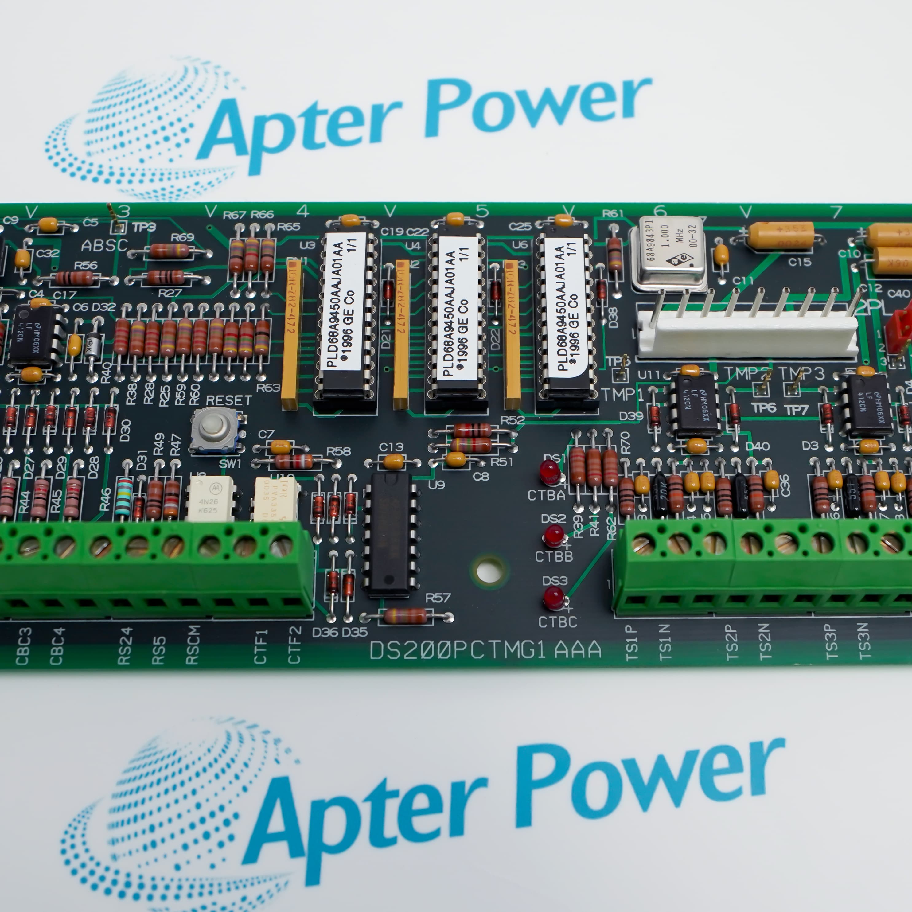
- Preserves the complete DS200PCTMG1AAA assembly marking as the controlling procurement identity.
- Uses terminal strips and cabinet connectors whose labels must be matched to the installed panel documentation.
- Requires the existing jumper, cable and revision positions to be recorded before the board is removed.
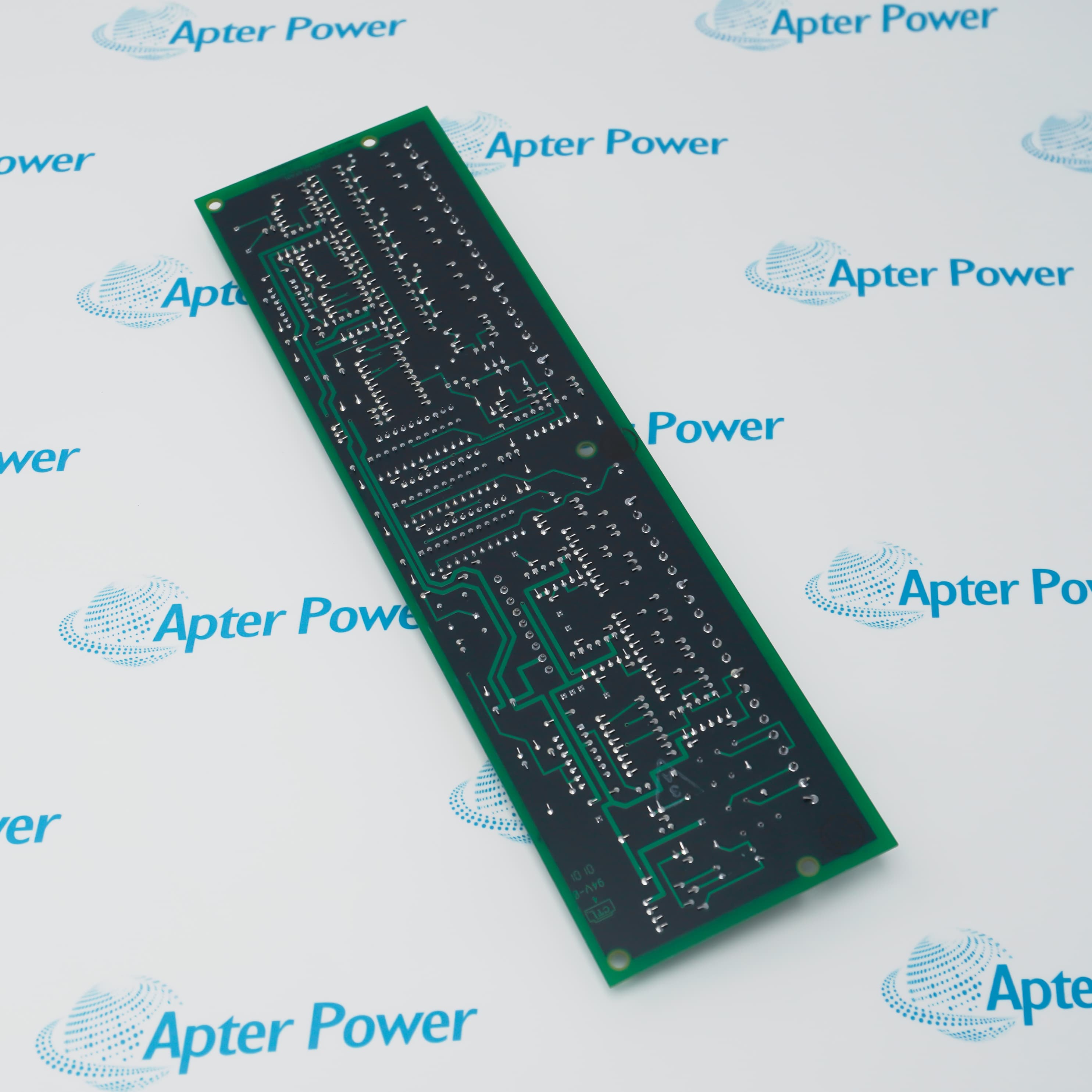
The current ordering configuration is DS200PCTMG1AAA, identified by the full marking on the supplied GE assembly rather than by the shared DS200 prefix alone.
It serves as removable electronic hardware within a project-specific SPEEDTRONIC Mark V cabinet, where the unit drawing and cable schedule define every connected circuit.
Before installation, compare the terminal designations, connector locations, jumper pattern, revision label and cabinet position with the removed board, then complete an approved functional check.
Availability is subject to Apter Power inventory and sourcing confirmation.
Verified resources for General Electric DS200PCTMG1AAA:
Important Notice: Other accessories, manuals, cables, calibration data, software, etc. are not included with this equipment unless listed in the above stock item description. All prices are shown in USD.
- Supports the legacy cabinet function assigned to this board in the installed turbine-control project.
- Serves maintenance and outage recovery where the exact printed-circuit assembly must be replaced without changing unrelated panel hardware.
- Provides a documented spare-management identity for plants extending Mark V service life while planning repair or migration.
- Compatibility is determined by the full board suffix, installed Mark V panel design and the project-specific control drawings.
- Connector count, terminal labeling, jumper positions and mating boards must match the removed assembly before fitment.
- A visually similar DS200 board or another PCTM suffix should not be treated as interchangeable without GE engineering evidence.
- The board is intended for installation inside the protected Mark V control cabinet rather than exposed field service.
- Cabinet temperature, cleanliness, grounding and ventilation must remain within the site documentation for the complete control panel.
- Handle and store the assembly using electrostatic-discharge controls and keep terminals and connectors free of contamination.
- Capture the original fault symptoms and controller diagnostics before board removal so wiring issues are not mistaken for PCB failure.
- Post-installation checks should confirm connector seating, terminal continuity, cabinet alarms and the assigned Mark V function.
- A controlled functional test is required because public GE documents do not provide a universal standalone test specification for this exact board.