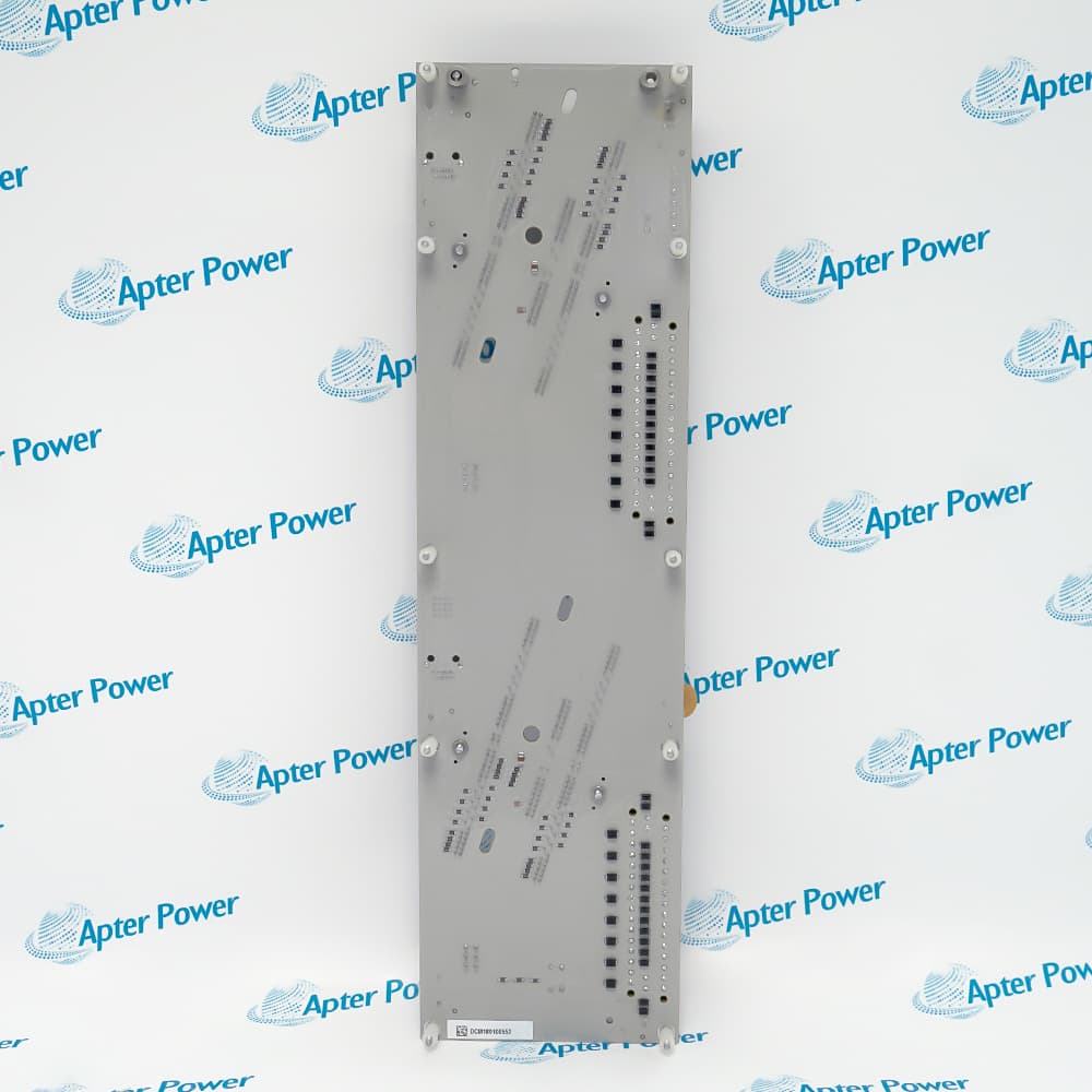
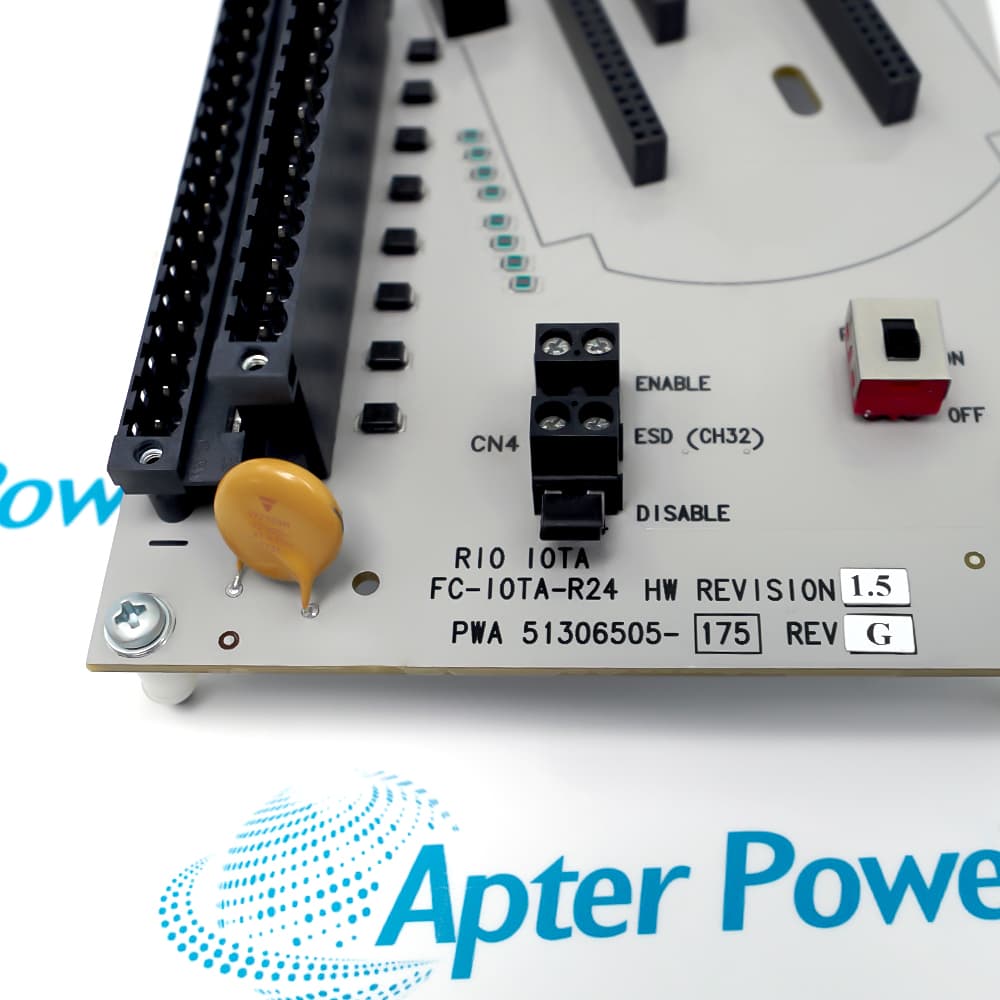
FC-IOTA-R24 51306505-175
Ask our team:
  • Phone: +86 181 0690 9650
  • E-Mail sales1@apterpower.com
  • Lifecycle status

    Active / Available from OEM
    Apter Power coordinates carrier identity, fuse condition, terminal mapping, and paired-module documentation for procurement review.

FC-IOTA-R24 51306505-175

/ 4.9
1001 reviews | Need a Specific Revision?
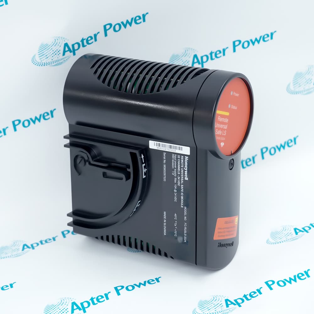
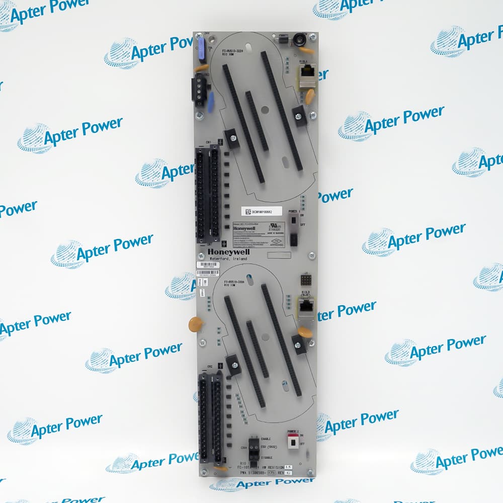
A redundant Safety Manager I/O pair reaches field wiring through FC-IOTA-R24 51306505-175, which combines module mounting, protected DC distribution and termination on one carrier.
In Stock
Ships by Thursday, October 29
Fast Shipping Available
Get a quick price for FC-IOTA-R24 51306505-175
Quantity
*E-mail
Company
*Mobile
*Content
Upload (gif, jpg, jpeg, png, bmp, doc, docx, xls, xlsx, ppt, pdf, csv)

Technical specifications for FC-IOTA-R24 51306505-175

  • Manufacturer:
    Honeywell
  • Part Number:
    FC-IOTA-R24 51306505-175
  • Product Family:
    Honeywell Safety Systems
  • Product Type:
    Redundant 24 V DC I/O Termination Assembly
  • Stock:
    1
  • Assembly role:
    Redundant I/O carrier and field termination
  • Nominal supply:
    24 V DC
  • Supply tolerance:
    -15% to +30%
  • Maximum supply current:
    10 A
  • Fuse:
    15 A, 32 V DC blade type
  • Protected V+ output:
    1 A total
  • Operating temperature:
    -40 to +70 °C
  • Relative humidity:
    10 to 95%, non-condensing
  • Weight:
    0.56 kg
  • Estimated shipping dimensions:
    44.2x12x6.5cm
  • Tariff Code:
    Please confirm the destination before shipping
  • Country of origin:
    USA
  • Place of shipment:
    Xiamen,Fujian,China
By purchasing this item, you agree to the Terms & Conditions, ApterPower is not an authorized distributor for listed manufacturers or tradenames and therefore the manufacturer's warranty does not apply. All our products come with ApterPower's 1-year warranty.

More Information

Overview Manuals Redundant Pairing Carrier Power Field Termination Product Applications

Features:

  • Redundant carrier: supports the documented paired I/O module arrangement
  • Protected field power: 24 V DC distribution through a replaceable 15 A fuse
  • Industrial environment: specified for -40 to +70 °C operation
FC-IOTA-R24 51306505-175 brings redundant I/O modules, protected power and field terminations together on one Safety Manager assembly.

Its engineering value depends on correct polarity, fuse selection, paired module placement and an exact terminal map rather than catalog-family similarity.

A replacement package should preserve label photographs, wiring records, supply measurements, fuse information and the commissioned redundancy arrangement.

Availability of FC-IOTA-R24 51306505-175 is subject to Apter Power inventory and sourcing confirmation.

Verified resources for FC-IOTA-R24 51306505-175:

Important Notice: Other accessories, manuals, cables, calibration data, software, etc. are not included with this equipment unless listed in the above stock item description. All prices are shown in USD.

  • Pair identity: record both installed module labels before removal.
  • Carrier position: preserve the documented slot and connector arrangement.
  • Switchover: test redundancy behavior under the site procedure.
  • Change control: retain wiring and project records with the replacement.
  • Input range: measure the supply inside the published tolerance.
  • Polarity: correct wiring before installation to avoid clearing the fuse.
  • Fuse: use the documented 15 A, 32 V DC blade type.
  • Output load: keep protected V+ pin demand within the stated total.
  • Terminal map: photograph and label every conductor before release.
  • Commons: preserve the documented reference and shielding arrangement.
  • Mechanical condition: inspect terminals, connectors and carrier guides.
  • Acceptance: prove channel continuity and redundancy after installation.
  • Safety Manager I/O: terminate field signals for an approved redundant pair.
  • Protected distribution: route 24 V DC through the documented carrier protection.
  • Maintenance replacement: restore a verified IOTA without remapping field wiring.
Description
Field wiring, protected supply distribution and redundant module mounting converge on FC-IOTA-R24 51306505-175 within Honeywell Safety Manager hardware. The assembly provides the physical carrier and termination boundary that keeps the paired I/O arrangement tied to a defined set of plant conductors.

The carrier structure of FC-IOTA-R24 51306505-175 keeps the two module positions, protected field-power path and plant terminals within one documented redundancy arrangement. This lets commissioning relate a channel problem to its paired module, shared carrier or field conductor without losing the termination map.

Before FC-IOTA-R24 51306505-175 is exchanged, the commissioning team should map the paired modules, conductor labels, commons, shields and supply polarity. The complete product identity matters because other FC-IOTA assemblies can use different termination and redundancy arrangements.
Alternative Names
Honeywell FC-IOTA-R24 51306505-175 Safety Manager FC-IOTA-R24 carrier FCIOTAR24 51306505175 Redundant 24 V Safety Manager IOTA
Technical notes
Reverse polarity is the highest installation risk for FC-IOTA-R24 51306505-175 because the protection clears its blade fuse. Measure polarity at the carrier before connection, use the documented fuse type, and confirm the protected V+ load remains within the approved field-power design before energizing the redundant pair.
Exceptional Service

Our Mission

  • 100% Satisfaction

    We believe expertise is priceless. With over 20 years of experience, and top engineers on staff, we can help you solve or avoid problems that threaten your business.
  • Trust Guaranteed

    Not only do we have a vast inventory, our team makes sure every piece of equipment is in working condition. Your purchases are also backed by our Warranty.
  • Expertise

    Time is money, especially when your equipment is down. We work quickly to get your equipment on its way so you can get it back up and running.

FAQS

The following is a list of questions commonly asked by our customers. Please contact us if you have a question about our process that is not answered below.
Why can FC-IOTA-R24 51306505-175 lose field power immediately after a maintenance reconnection?
Reverse polarity can clear the carrier fuse. Isolate the supply, measure polarity at the assembly, inspect the fuse and wiring, and do not re-energize until the cause is corrected.
How should FC-IOTA-R24 51306505-175 be documented before a redundant module pair is disturbed?
Record both module positions, the carrier label, each field terminal, commons, shields, protected-power conductors and the approved switchover test used by the site.
What should engineers investigate when channels on both modules fitted to FC-IOTA-R24 51306505-175 fail together?
Begin with the shared carrier supply, fuse, protected V+ distribution and common wiring before replacing both I/O modules independently.
Can a visually similar Safety Manager carrier replace FC-IOTA-R24 51306505-175 without remapping field conductors?
No. Match the complete product identity, terminal map, paired-module arrangement and power distribution; family resemblance does not prove the same termination design.
How should protected loads be reviewed when additional field devices are connected through FC-IOTA-R24 51306505-175?
Total the demand on the protected V+ path under worst-case operation, compare it with the documented design and move the load elsewhere if the carrier boundary would be exceeded.
What acceptance test should follow installation of FC-IOTA-R24 51306505-175 in a redundant assembly?
Confirm supply stability, channel continuity and terminal identity, then execute the approved redundancy and switchover procedure before returning the pair to production.

Product Browsing History