Features:
- Vertical I/O Bus Extension from Controller Chassis to Multiple I/O Chassis
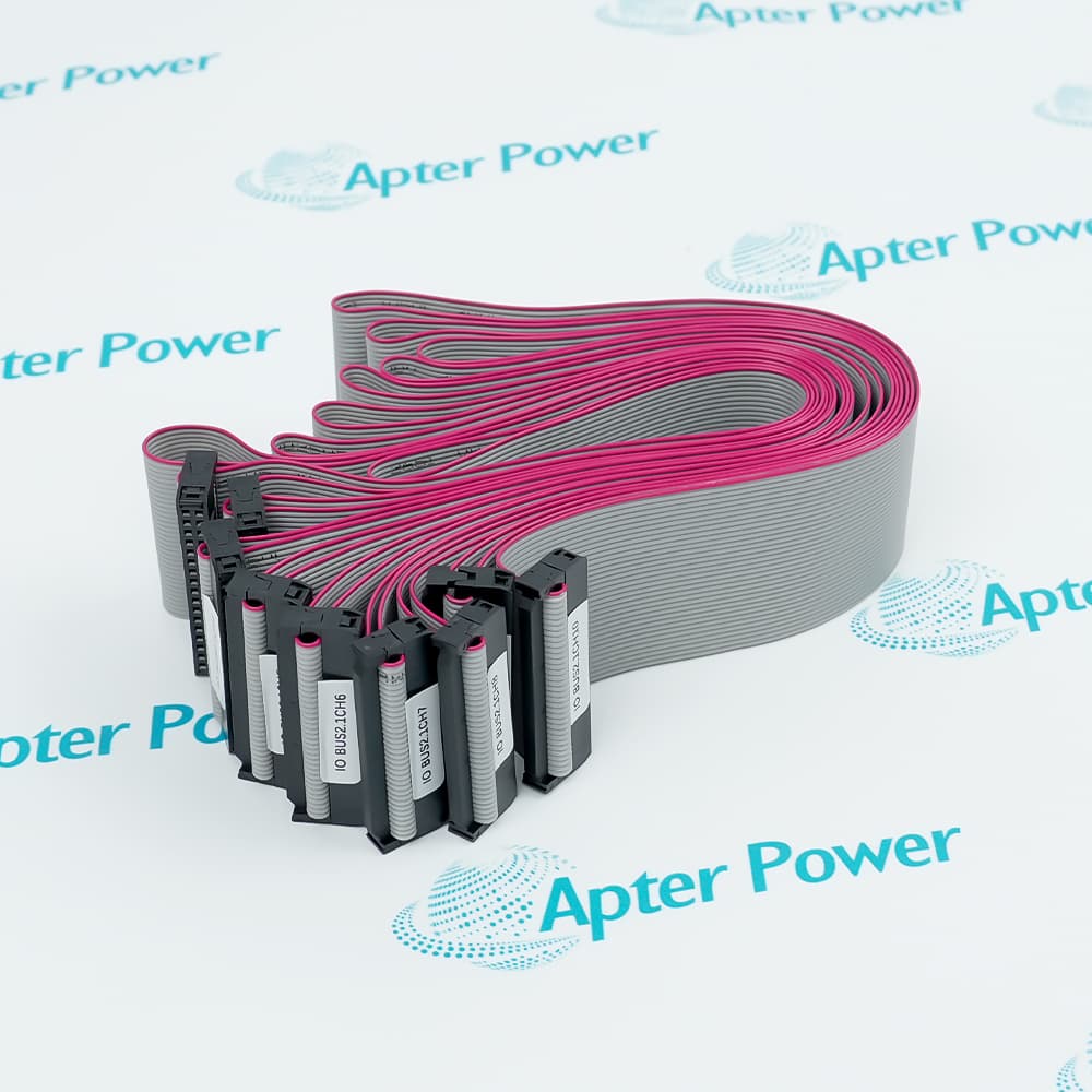
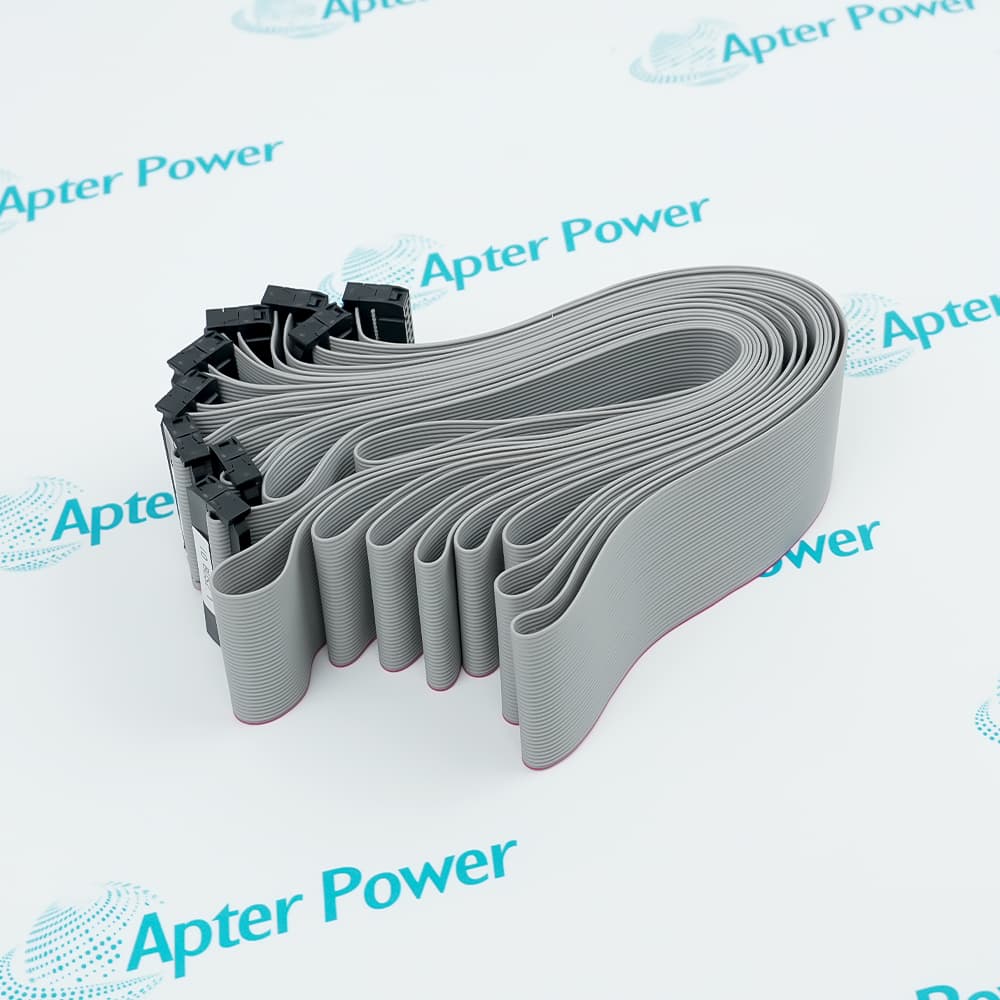
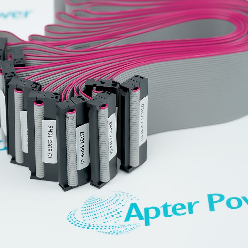
- Combines 34-Wire Flat Cable Design with Secure Latch Connector Interface
- Operates in Conjunction with the CPCHAS-0001 and IOCHAS-0001S/R Chassis
The FS-IOBUS-CPIO functions as the dedicated I/O bus extension cable within Honeywell control systems, establishing reliable communication pathways between the controller chassis and distributed I/O chassis units. It continuously routes all scan, test, and update actions between the QPP module and connected I/O modules through its 34-conductor flat cable architecture. Seamless data transmission is standard with the FS-IOBUS-CPIO, ensuring uninterrupted signal integrity across extended physical distances between chassis units.
The FS-IOBUS-CPIO provides essential connectivity functions critical to the entire I/O network architecture, serving as a fundamental component of the control path that directly affects the proper, normal operation of the overall monitoring and control system. One or multiple FS-IOBUS-CPIO cables are utilized depending on the number of I/O chassis requiring connection to the primary controller. The FS-IOBUS-CPIO features a 34-pole latch female connector designed for secure physical attachment within industrial cabinet installations.
For Multi-Chassis I/O Extension applications, the control system requires FS-IOBUS-CPIO cables to interconnect the CPCHAS-0001 controller chassis with one or more IOCHAS-0001S/R I/O chassis units. In addition to standard point-to-point connectivity, the FS-IOBUS-CPIO configuration supports distributed I/O architectures across extension cabinets. The FS-IOBUS-CPIO cabling system executes reliable signal transmission using the internal 34-wire conductor specification detailed in the product documentation. Using this method, the I/O bus extension maintains continuous communication between the QPP module and remote I/O modules, ensuring all scan, test, and update operations complete successfully across the extended chassis configuration.
The FS-IOBUS-CPIO Honeywell I/O Bus Controller may still be available for purchase and support from Apter Power beyond End-Of-Life (EOL) by the manufacturer (OEM).
Honeywell FS-IOBUS-CPIO I/O Bus Controller Manuals, Datasheets, Drivers, Link
Important Notice: Other accessories, manuals, cables, calibration data, software, etc. are not included with this equipment unless listed in the above stock item description. All prices are shown in USD.
Honeywell FS-IOBUS-CPIO I/O Bus Controller Specs
General
- Manufacturer Honeywell
- Model FS-IOBUS-CPIO
- Condition New Original ready stock
- Product Family
FS-IOBUS-CPIM,FS-IOBUS-CPIS,FS-IOBUS-RIO
Important Notice: Other accessories, manuals, cables, calibration data, software, etc. are not
included with this equipment unless listed in the above stock item description. All prices are
shown in USD.
- Emergency Shutdown Systems (ESD): In oil and gas, refineries, and chemical plants, responsible for handling the shutdown logic communication at critical nodes.
- Fire and Gas Monitoring (F&G): Integrates detector signals to ensure rapid activation of fire interlocks in the event of a hazard.
- Burn Management Systems (BMS): Used in power plants or large boilers to monitor flame status and valve synchronization.
- Redundant Communication Links: In dual or triple redundancy architectures, manages data synchronization and path switching between I/O racks.
- Firmware Version Consistency: In redundant systems, master and slave modules must run the same firmware version; otherwise, synchronization failure or system alarms may occur.
- Loading Tool: Typically performed remotely via Honeywell's Safety Builder software.
- Offline/Online Updates: While some architectures support online upgrades, for absolute safety, firmware flash updates are recommended during system maintenance or factory downtime.
- Engineering Tools: Primarily uses the Safety Builder software environment for configuration.
- Station Address Setting: Define I/O bus addresses via hardware jumpers or software parameters on the module.
- Bus Parameter Optimization: Configure communication scan time and timeout monitoring thresholds to meet safety response time requirements.
- Diagnostic Mapping: Map the module's health status (such as voltage anomalies, packet loss) to system variables for real-time monitoring on the HMI.