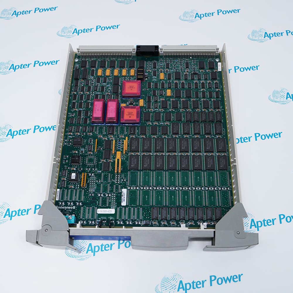
Features:
- Bridge Between the Local Control Network (LCN) and Universal Control Network (UCN)
- Integrates High-Speed Data Exchange with Protocol Conversion and Network Management
- Works in Conjunction with the K4LCN Processor and NIM Modem I/O Cards
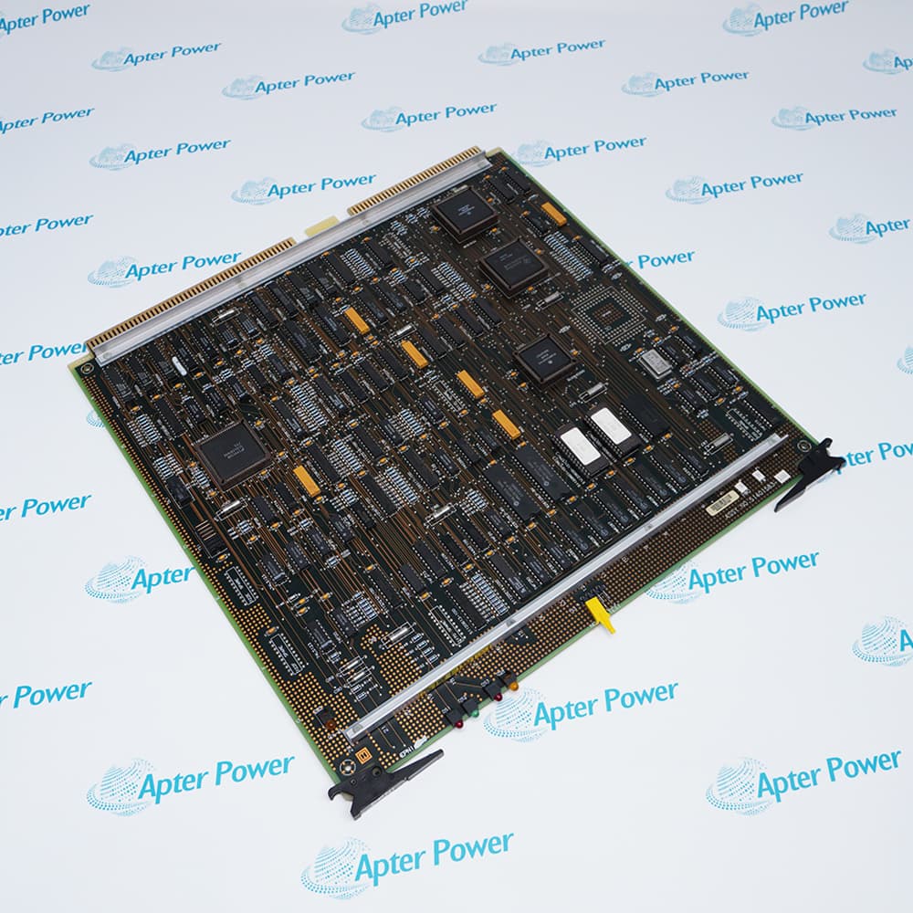
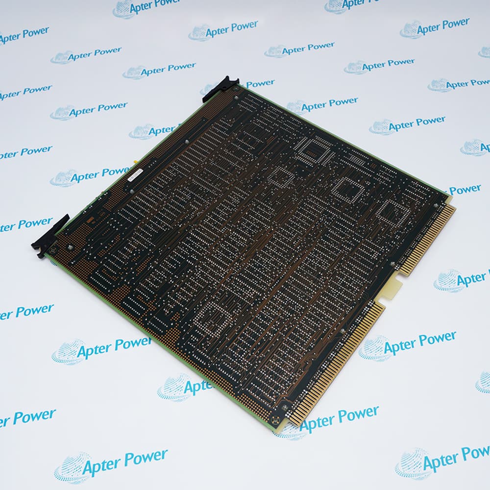
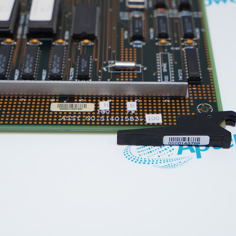
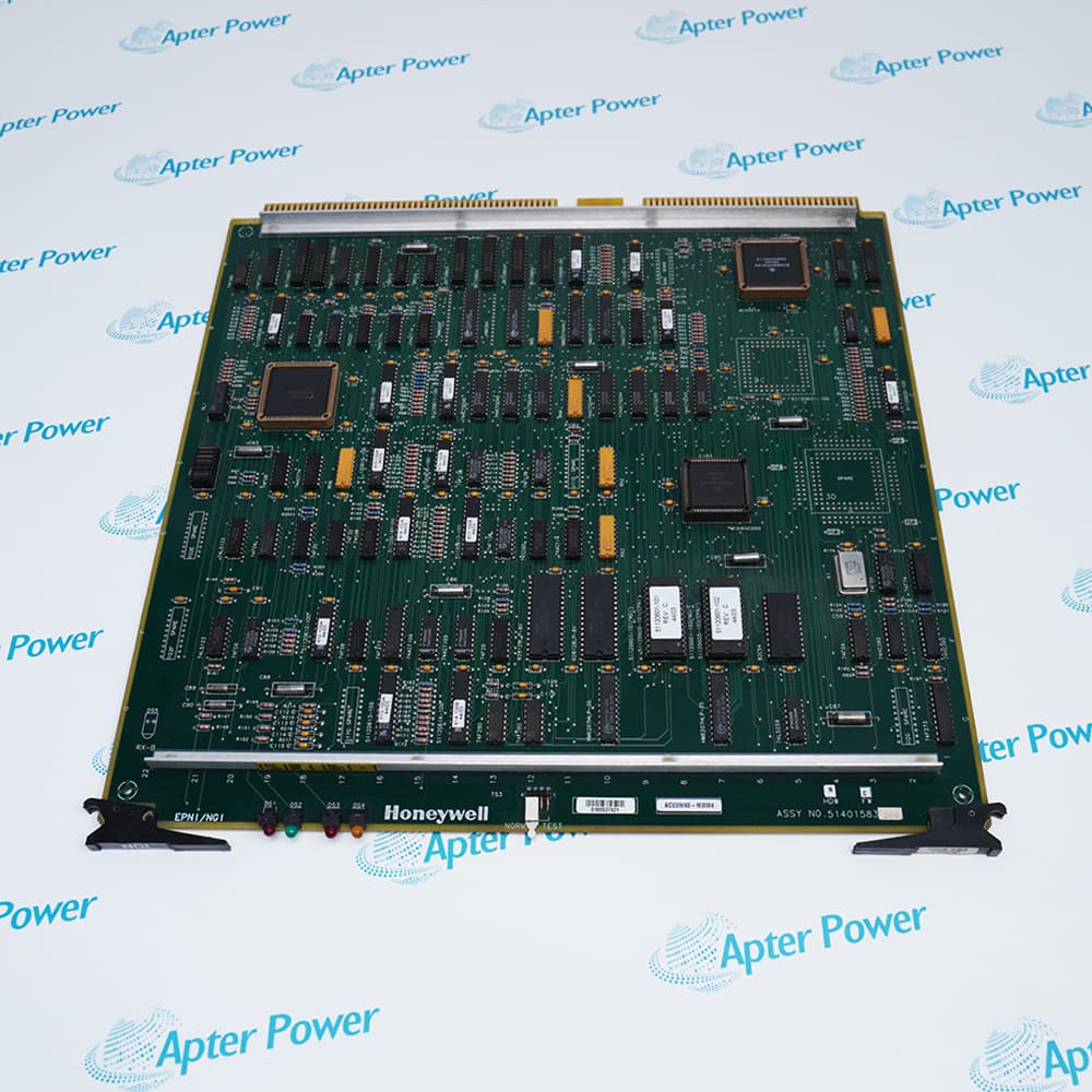
The Honeywell 51401583-100 Enhanced Process Network Interface Board serves as the primary logic board for the Network Interface Module (NIM) in Honeywell's distributed control systems. The 51401583-100 continuously bridges the Local Control Network (LCN) and the Universal Control Network (UCN), enabling seamless transmission of control signals, process data, and point database information between these network layers. For applications requiring Sequence of Events (SOE) time synchronization, the 51401583-100 must be equipped with firmware version 'H' to ensure precise operation. The 51401583-100 has made improvements in network communication capability within the Honeywell control architecture, incorporating robust protocol conversion and network management functions.
The 51401583-100 provides essential network interface functions common to the entire distributed control system, and is a critical component of the communication path, directly affecting the proper, normal operation of the overall monitor system. One or two 51401583-100 boards are typically deployed per NIM node depending on the desired redundancy level. The 51401583-100 occupies a dedicated slot within the NIM assembly and is always paired with the K4LCN processor to form a complete network interface node.
For Dual Redundant NIM applications, the Honeywell system requires a second NIM assembly installed in the redundant configuration. In addition to standard single NIM operation, the redundant configuration also performs automatic switchover. The dual NIM configuration executes failover using the internal circuitry specified in the system options. Using this method, the redundant network interface system continually monitors the health of both NIM assemblies. If the system detects that the primary 51401583-100 is no longer providing stable network communication (outside configured tolerance levels), it will automatically transfer the network load to the secondary supply and place an event in the System Event List.
The 51401583-100 Honeywell Enhanced Process Network Interface Board may still be available for purchase and support from Apter Power beyond End-Of-Life (EOL) by the manufacturer (OEM).
Honeywell 51401583-100 Enhanced Process Network Interface Board Manuals,Datasheets,Link
Important Notice: Other accessories, manuals, cables, calibration data, software, etc. are not included with this equipment unless listed in the above stock item description. All prices are shown in USD.
Honeywell 51401583-100 Enhanced Process Network Interface Board Specs
General
- Manufacturer Honeywell
- Model 51401583-100
- Condition New Original ready stock
- Product Family 51401551-301 ,51401551-400,51401551-600 ,51401551-601
Important Notice: Other accessories, manuals, cables, calibration data, software, etc. are not included with this equipment unless listed in the above stock item description. All prices are shown in USD.
- Industrial Automation & Process Control: Used in oil refineries, power plants, and chemical processing facilities to interconnect xPM and LM nodes with central point databases.
- Sequence of Events (SOE): Specifically required for applications needing millisecond-accurate time synchronization across decentralized nodes (requires firmware revision 'H' or higher).
- System Upgrades: Replaces older PNI and PNM board sets to consolidate functions and improve network reliability.
- Node Definition: During system setup, UCN points and node-specific points (defining the NIM and PM nodes on that UCN) are built to establish where the network resides.
- Load Estimation: Engineers must calculate a NIM load estimate by multiplying the node count by a specific Load Factor to prevent network overloads.
- Slot Assignment: In a standard 3/3/2/2 Multinode Module configuration, the EPNI board is typically installed in specific slots (e.g., slots 2, 5, 8, or 10) depending on the redundancy setup.
- Visual Indicators: It includes status LEDs such as SELF TST/ERR (red) and PASS MOD TEST (green). A red light typically indicates a hardware failure, RAM parity error, or duplicate address detection.
- Network Bridging Control: It manages the flow of messages from the UCN to the LCN and vice versa, ensuring that operators at the Universal Station (US) have a continuous view of process variables.
- Redundancy Management: Usually deployed in redundant pairs; the board manages automatic switchover to ensure the link between network tiers remains active during a hardware failure.