Features:
- Bridges Honeywell TDC 3000 Local Control Network (LCN) to external plant-wide networks; enables data integration with MES, ERP, or other information systems.
- Standard form factor for TDC 3000 five-slot or ten-slot chassis; compatible with existing backplane and power supply.
- Allows older TDC 3000 DCS to communicate with modern IT infrastructure without replacing the entire control system; extends life of legacy investment.
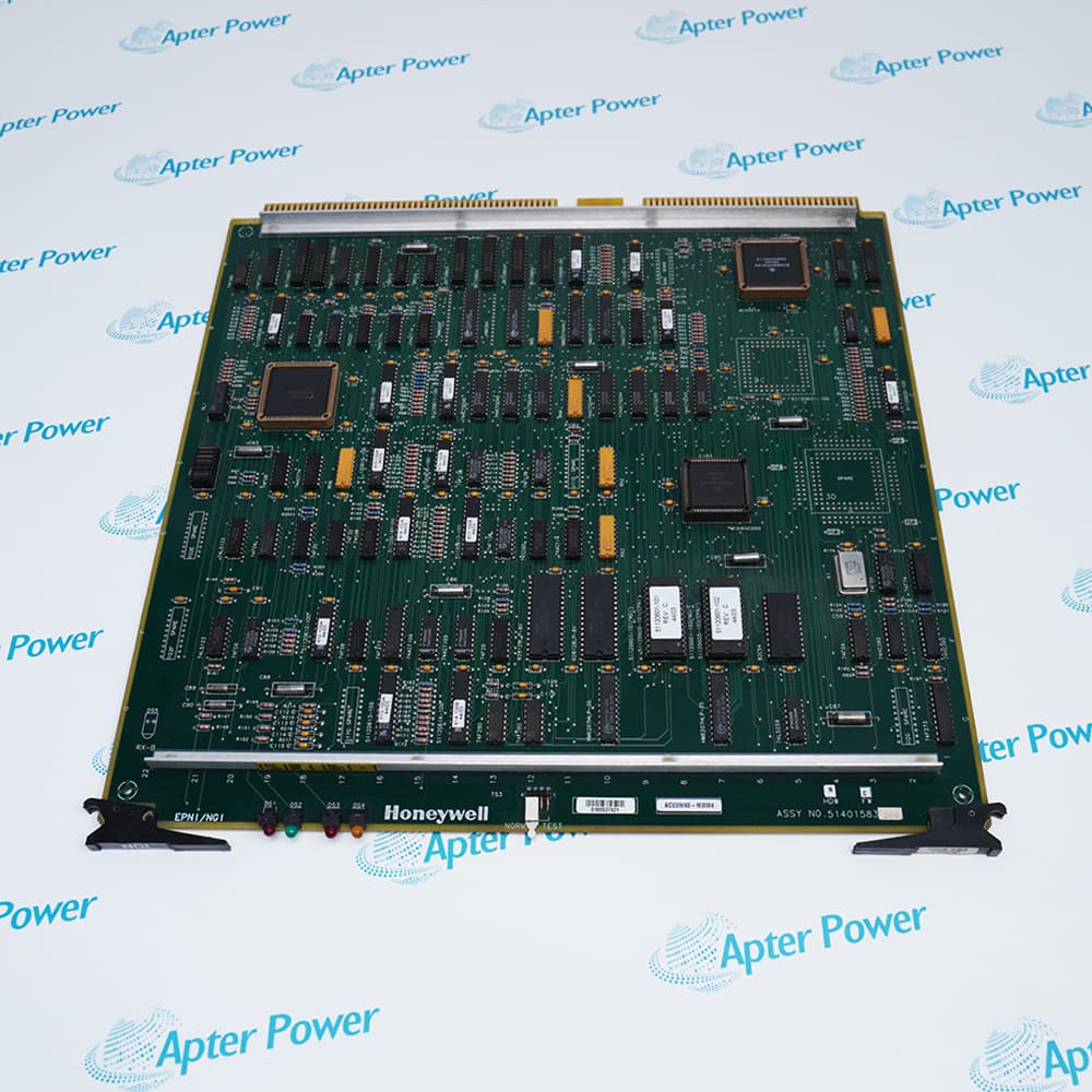
The 51401583-200 serves as a Network Gateway Interface (NGI) between Honeywell's Local Control Network (LCN) and external plant networks. The LCN is the high-speed, deterministic network that connects nodes within a TDC 3000 system, including consoles, application modules, and history modules. While LCN is excellent for real-time control, it is a proprietary network not directly compatible with standard IT networks. The 51401583-200 solves this by providing a gateway that translates LCN protocols into formats (such as TCP/IP) usable by plant information systems.
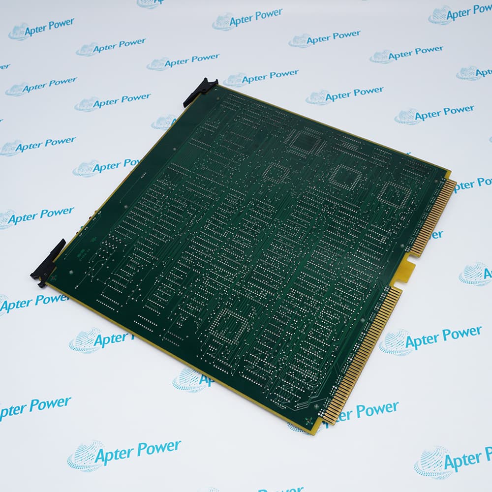
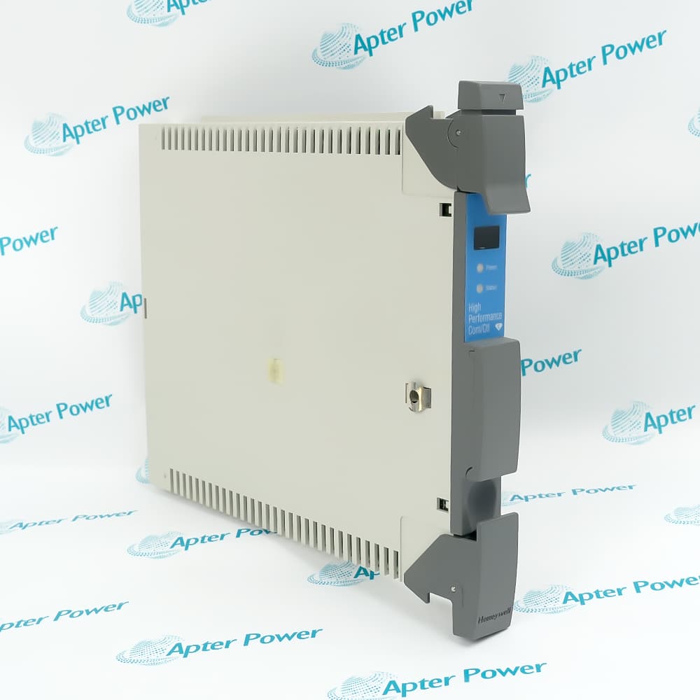
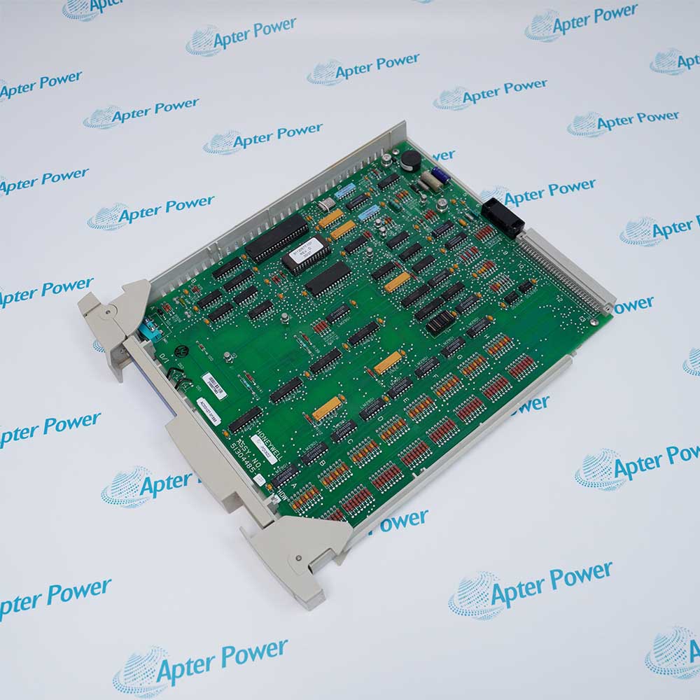
The 51401583-200 is designed as a functional board for Honeywell's TDC 3000 system, specifically for use in five-slot or ten-slot chassis. TDC 3000 was a pioneering distributed control system (DCS) widely used in refineries, chemical plants, and power generation. Functional boards like the NGI plug directly into the chassis backplane, receiving power from the system power supply and communicating over the LCN bus. The board's form factor is standardized, allowing it to be installed alongside other functional boards such as Enhanced Microprocessor (EMPU), Memory (MEM), or Communications Network Interface (CNI).
TDC 3000 systems have been in operation for decades, and many plants continue to rely on them for critical process control. However, modern plant management requires data integration with higher-level systems. The 51401583-200 provides a path for these legacy DCS installations to communicate with modern IT infrastructure without a costly, disruptive system replacement. The board acts as a gateway, translating LCN data packets into formats recognized by external networks. This enables operations teams to view real-time process data on modern HMIs, allows maintenance teams to access alarm history from a central server, and provides production data to MES for performance analysis.
The 51401583-200 Honeywell Network Gateway Interface may still be available for purchase and support from Apter Power beyond
End-Of-Life (EOL)by the manufacturer (OEM).
Honeywell 51401583-200 Network Gateway Interface Manuals,
Datasheets,Drivers,Link
Important Notice:Other accessories,manuals,cables,calibration data,software,etc.are not
included with this equipment unless listed in the above stock item description.All prices are
shown in USD.
Honeywell 51401583-200 Network Gateway Interface Specs
General
- Manufacturer Honeywell
- Model 51401583-200
- Condition New Original ready stock
- Product Family
51401583-100,51400955-100,51401088-100
Important Notice:Other accessories,manuals,cables,calibration data,software,etc.are not
included with this equipment unless listed in the above stock item description.All prices are
shown in USD.
- Cross-network communication: Establishes communication bridges between different LCN segments, supporting multi-node parameter transmission and file transfer.
- Industrial Information Network (PIN) integration: Supports network connections compliant with the IEEE 802.4 standard, including carrier networks (such as UCNs used in NIM and Process Manager) and fiber optic star networks.
- Data processing centers: Features high throughput, processing up to 1,200 point parameters per second and supporting file transfer operations of 12,000 words per second.
- LED Status Indicators: The panel features SELF TST/ERR (Self-Test/Error) and PASS MOD TEST (Module Passed Test) indicators to display the module's operating status in real time.
- Fault Isolation: Parameter transmission and file transfer are controlled by independent internal channels, ensuring that high load on one task will not affect the communication stability of another channel.
- Self-Test Procedure: A self-test is performed during system startup or operation. If the SELF TST/ERR indicator remains lit, it indicates that the NGI or NGIO backplane needs to be replaced.
- Physical Installation:
Modules are typically installed in slots within a Multinode Module or Enhanced Micro TDC 3000 tower rack.During installation, ensure the NGIO backplane is correctly installed and that the NGI module is aligned with its slot.
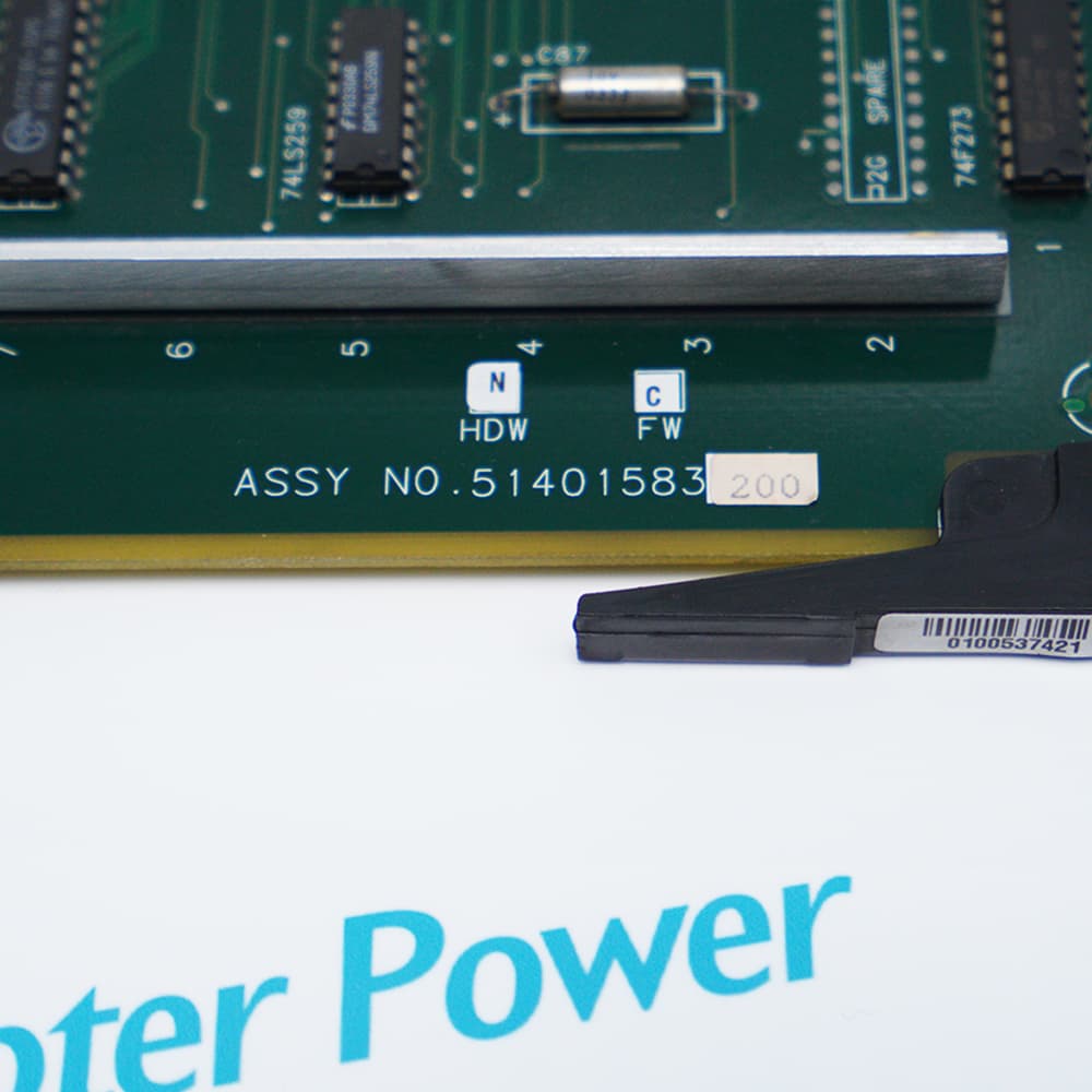
- Version and Compatibility: Common hardware revisions (F) and firmware revisions (C) are used.When upgrading or replacing, ensure the hardware/firmware revision numbers of the old and new modules match to maintain system interoperability.