Features:
- Up to 12 digital intercom stations share one DXC line-card position.
- Permanent supervision detects station-cable interruption and short circuit.
- Hot-swappable construction supports card service within the documented DXC procedure.
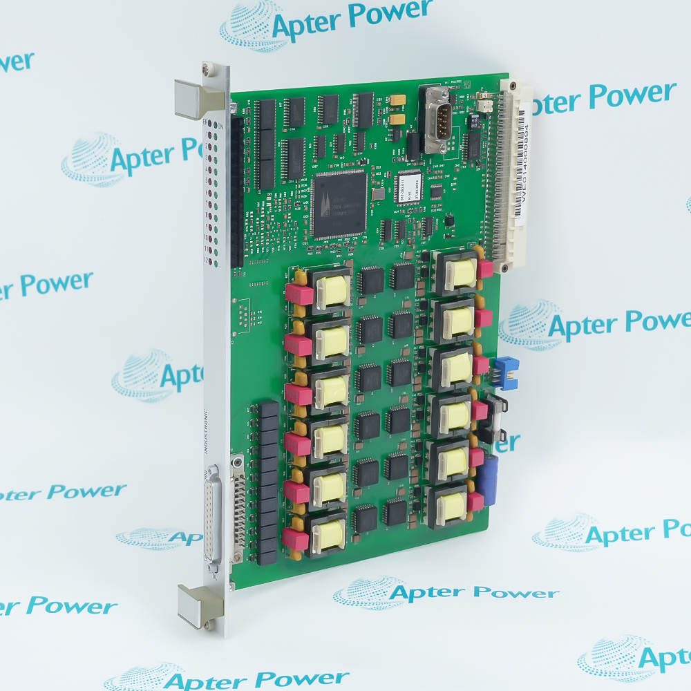
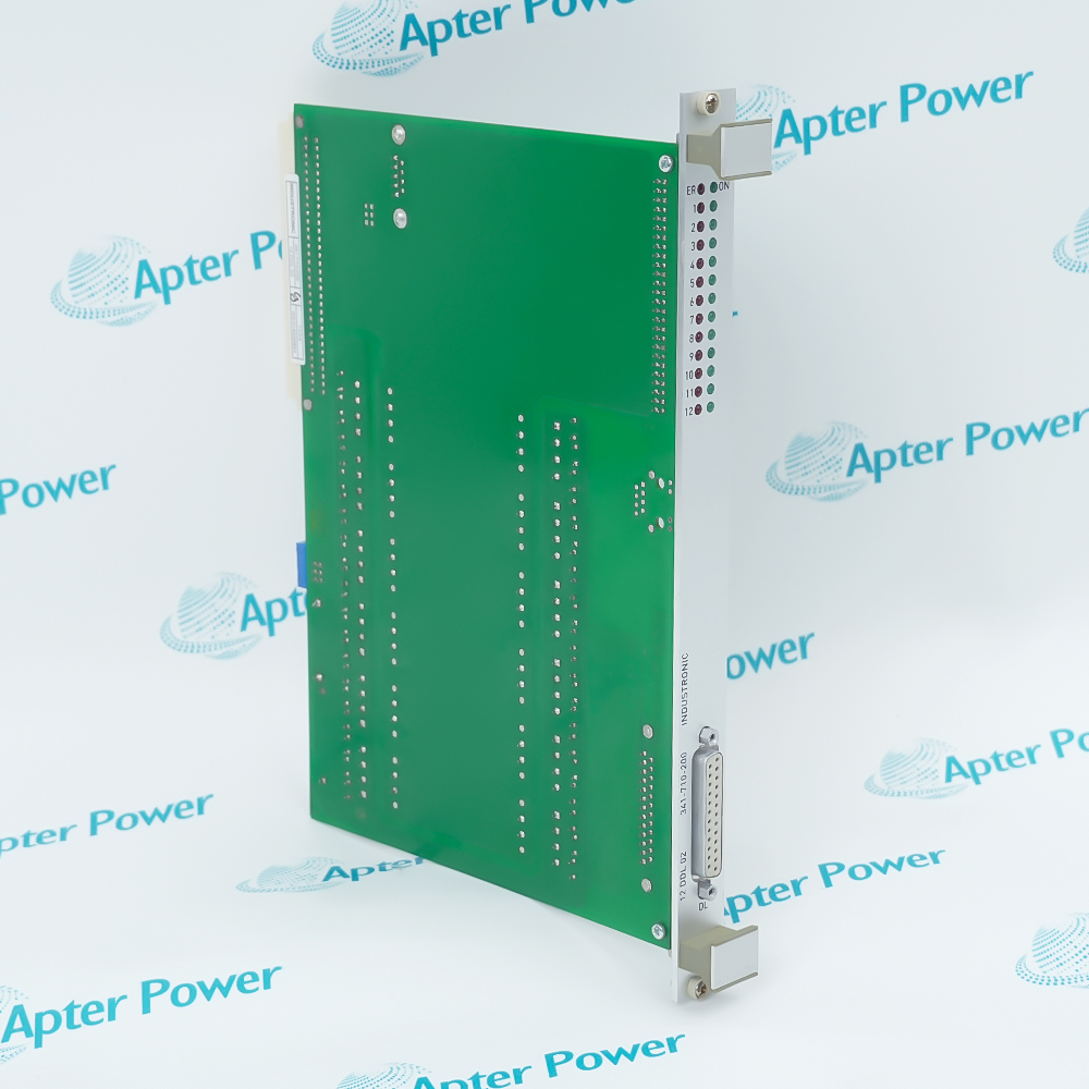
The 12 DDL 02 layout groups twelve monitored station paths behind one front 25-pin Sub-D connection.
Card-level LEDs report operation or failure, while paired indicators for each station separate AF traffic from a local fault.
A PC612-C64 backplane plug carries chassis connections, leaving the RS232 connector and software-update slot accessible at the front.
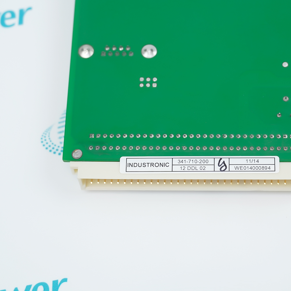
The INDUSTRONIC 12 DDL 02 341-710-200 Digital Line Card may still be available for purchase and support from Apter Power beyond End-Of-Life (EOL) by the manufacturer (OEM).
INDUSTRONIC 12 DDL 02 341-710-200 Digital Line Card Manuals,Datasheets,Link
Important Notice: Other accessories, manuals, cables, calibration data, software, etc. are not included with this equipment unless listed in the above stock item description. All prices are shown in USD.
How the twelve station lines are organized
- Line count: One card manages as many as 12 digital intercom stations.
- Signal transport: Each line carries digitized AF and control information.
- Separation: Transmission lines are galvanically isolated from the card electronics.
- Station power: The line card supplies the connected intercom terminals within the documented current limit.
Reading card and station indications
- Operation: The card-level green LED indicates normal operation.
- Card failure: A red card-level LED reports a general failure condition.
- AF traffic: One green indicator per station shows incoming or outgoing audio activity.
- Station fault: One red indicator per line identifies a station-specific failure.
Separating service and operating connections
- Controller link: HDLC carries communication between the line card and DXC controller.
- Service access: RS232 is reserved for the documented maintenance interface.
- Station harness: A 25-pin Sub-D female connector terminates the field station lines.
- Chassis plug: The PC612-C64 connector mates the card to the DXC backplane.
Checks before seating the card
- Slot envelope: Allow for a 6 RU, 4 HP front plate and the documented card depth.
- Terminal supply: Confirm the station source remains between 48 and 72 V.
- Thermal range: Keep cabinet operation from 0 °C to +50 °C.
- Post-service test: After a hot swap, verify card LEDs and every station line before returning the exchange to service.