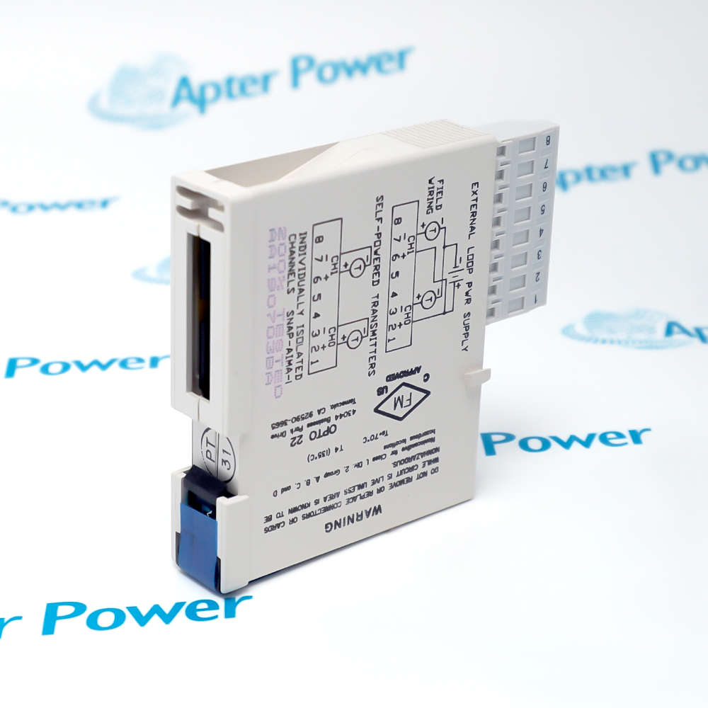
SNAP-AIMA-I
SNAP-AIMA-I
SNAP-AIMA-I
SNAP-AIMA-I
SNAP-AIMA-I
SNAP-AIMA-I
Ask our team:
  • Phone: +86 181 0690 9650
  • E-Mail sales1@apterpower.com
How We Verify Your Order
Before dispatch, we confirm the exact model, revision, condition, inspection requirements and shipping documents for your order.
See a real on-site verification case >>
  • Lifecycle status

    Active / Available from OEM
    Apter Power supports SNAP-AIMA-i quotations, loop-design documentation and SNAP I/O module matching.

SNAP-AIMA-i

/ 4.9
1001 reviews | Need a Specific Revision?
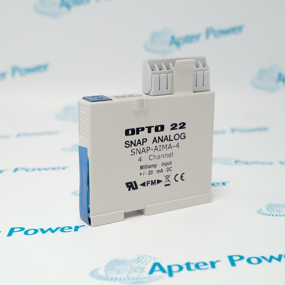
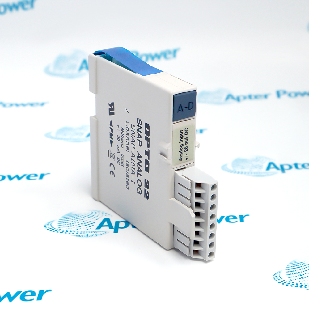
OPTO22 SNAP-AIMA-i is a two-channel isolated analog input module for bipolar current measurements in SNAP I/O systems.
In Stock
Ships by Saturday, November 14
Fast Shipping Available
Get a quick price for SNAP-AIMA-i
Quantity
*E-mail
Company
*Mobile
*Content
Upload (gif, jpg, jpeg, png, bmp, doc, docx, xls, xlsx, ppt, pdf, csv)

Technical specifications for SNAP-AIMA-i

  • Manufacturer:
    OPTO22
  • Part Number:
    SNAP-AIMA-i
  • Product Family:
    SNAP Analog Input Modules
  • Product Type:
    Isolated Analog Current Input Module, 2 Channels
  • Stock:
    1
  • Input channels:
    2 isolated analog current inputs
  • Signal range:
    -20 mA to +20 mA
  • Loop excitation:
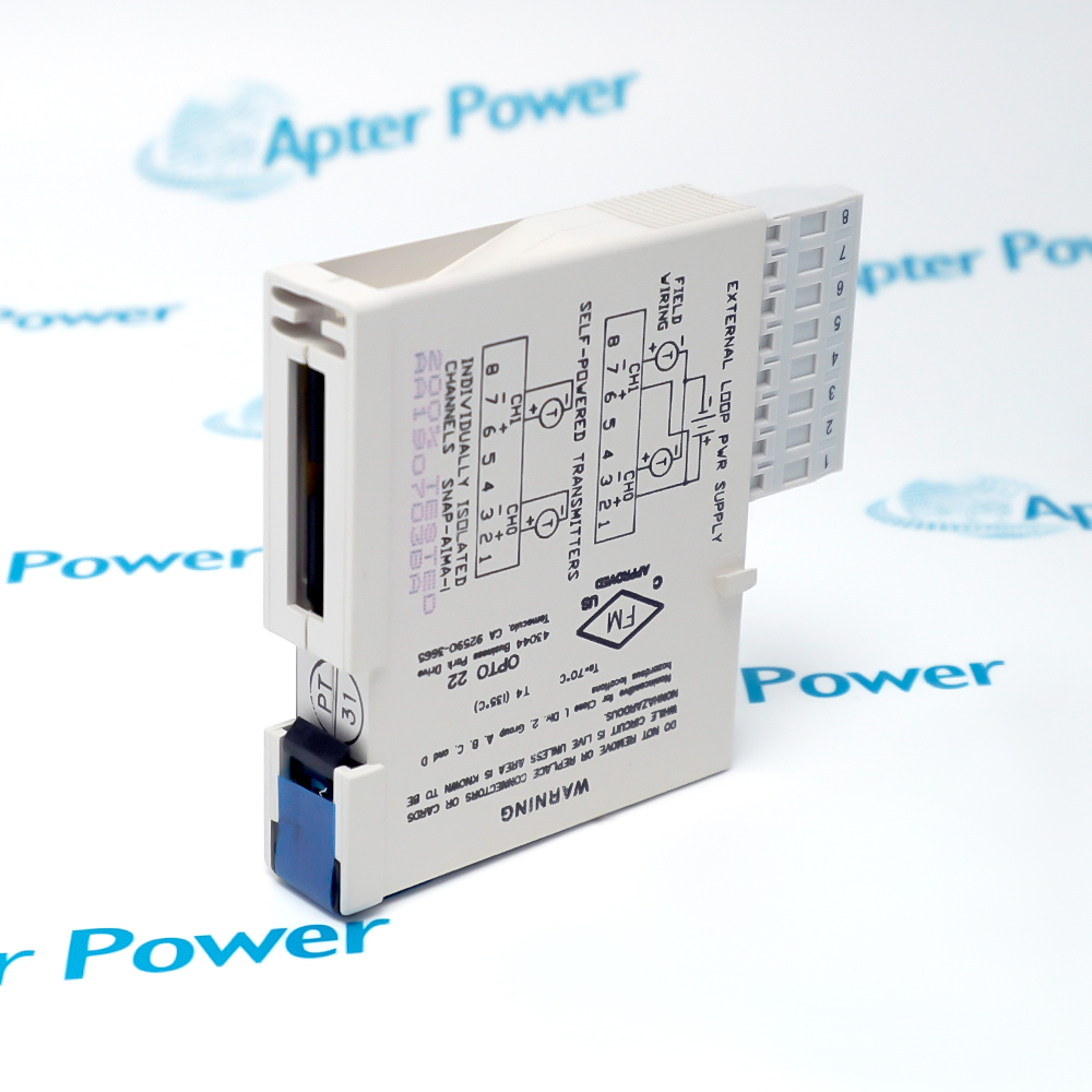
    None; external loop power required
  • Resolution:
    0.8 µA
  • Data freshness:
    11 ms
  • Accuracy:
    ±0.05% of full scale
  • Input resistance:
    200 Ω
  • Isolation:
    Channel-to-channel and field-to-logic isolation
  • Weight:
    0.1 kg
  • Estimated shipping dimensions:
    8.255 x 9.017 x 1.829 cm
  • Tariff Code:
    8537101190
  • Country of origin:
    USA
  • Place of shipment:
    Xiamen,Fujian,China
By purchasing this item, you agree to the Terms & Conditions, ApterPower is not an authorized distributor for listed manufacturers or tradenames and therefore the manufacturer's warranty does not apply. All our products come with ApterPower's 1-year warranty.

More Information

Overview Manuals Current Loop Design Isolation Boundaries Point Commissioning Product Applications

Features:

  • Two isolated channels: separates field-current measurements for controlled troubleshooting.
  • Bipolar current range: supports approved negative and positive current signals within one module.
  • External loop power: keeps excitation design explicit instead of hiding it inside the input module.
SNAP-AIMA-i is used when two current-loop measurements need channel separation inside a SNAP I/O station. The module receives the field current but does not energize the loop, so the external supply and transmitter wiring remain part of the complete circuit.

During commissioning, SNAP-AIMA-i should be tested with one stable current source at a time. Comparing the injected current, controller raw value and engineering scaling helps distinguish wiring or configuration errors from module behavior.

For an operating rack, SNAP-AIMA-i records should capture slot position, point duty, polarity and the source of loop power. That context makes future fault isolation safer and faster.

Technical support: Share the SNAP rack type, slot, loop drawing and observed current value when requesting application review.
OPTO22 SNAP-AIMA-i Isolated Analog Current Input Module, 2 Channels Manuals,Datasheets,Link
Important Notice: Other accessories, manuals, cables, calibration data, software, etc. are not included with this equipment unless listed in the above stock item description. All prices are shown in USD.
  • External excitation: every connected transmitter or current source must have an approved field-power path.
  • Voltage budget: source voltage must cover transmitter demand, cable loss and the documented input resistance.
  • Polarity control: terminal orientation and configured signal direction must agree before the point is released.
  • Bipolar duty: negative current measurements require the complete source and controller scaling to support that operating region.
  • Channel separation: testing one input at a time helps keep field faults localized.
  • Logic separation: field circuits remain isolated from SNAP-side logic within the documented module design.
  • Shield practice: cabinet grounding and shield termination must follow the site instrumentation standard.
  • Stable source: inject known current values across the intended span before enabling automatic control.
  • Raw-value check: compare the controller input count with the configured engineering conversion.
  • Loop record: document polarity, external supply and point assignment after the test passes.
  • Process transmitters: receives externally powered current signals from pressure, flow, level and analytical instruments.
  • Bipolar current sources: acquires approved negative and positive current measurements for specialized plant equipment.
  • Two-point expansions: adds isolated current capacity without allocating a larger analog module.
  • Diagnostic test stations: supports controlled current injection when loop behavior must be separated from transmitter performance.
Description
When two current loops need to remain electrically independent, SNAP-AIMA-i provides channel-to-channel isolation across its two bipolar current inputs. This helps prevent one field loop from becoming the shared electrical reference for the other.

Because SNAP-AIMA-i does not provide loop excitation, it fits externally powered measurement circuits where the power source and signal path are designed separately. That boundary also distinguishes it from loop-sourcing variants during module selection.

During commissioning, the bipolar range of SNAP-AIMA-i allows controlled current injection in either direction while its two-channel architecture keeps the test localized. The result is a clearer distinction between loop wiring, controller scaling and module response.
Alternative Names
Opto 22 SNAP-AIMA-i OPTO 22 SNAP-AIMA-i SNAP AIMA i SNAP-AIMA-i analog input module 2-channel isolated current input module OPTO22 part SNAP-AIMA-i
Technical notes
SNAP-AIMA-i does not provide loop excitation. Before energizing a channel, verify the external current-loop supply, polarity, terminal assignment and controller scaling with the approved SNAP I/O wiring documentation.
Exceptional Service

Our Mission

  • 100% Satisfaction

    We believe expertise is priceless. With over 20 years of experience, and top engineers on staff, we can help you solve or avoid problems that threaten your business.
  • Trust Guaranteed

    Not only do we have a vast inventory, our team makes sure every piece of equipment is in working condition. Your purchases are also backed by our Warranty.
  • Expertise

    Time is money, especially when your equipment is down. We work quickly to get your equipment on its way so you can get it back up and running.

FAQS

The following is a list of questions commonly asked by our customers. Please contact us if you have a question about our process that is not answered below.
A powered transmitter is wired to SNAP-AIMA-i but the controller remains at zero. Where should diagnosis begin?
Confirm that the loop has an external power source, then check polarity, terminal assignment and whether the injected current actually reaches the module input.
Two SNAP-AIMA-i channels connected to the same reference source disagree. How should the test be separated?
Test one channel at a time with the same calibrated source and lead set, then compare controller scaling before attributing the difference to the module.
A SNAP-AIMA-i point clips near the top of its range even though the field reading looks normal. Which settings deserve review?
Compare the actual loop current with the configured engineering span and confirm that neither the source nor the controller scaling assumes a unipolar range.
Noise appears on a SNAP-AIMA-i loop only after a cabinet wiring change. What should be checked first?
Inspect shield termination, common routing, grounding and the new cable path before changing filtering or calibration values.
A plant is adding SNAP-AIMA-i to a mixed SNAP I/O rack. Which installation records should be prepared?
Record the rack position, point assignment, external loop-power source, terminal polarity and controller scaling for each of the two channels.
The controller value from SNAP-AIMA-i seems slower than the injected current step. How should the behavior be judged?
Allow for the documented data-freshness interval and controller scan path, then compare a stable input at several points instead of judging one fast transient.