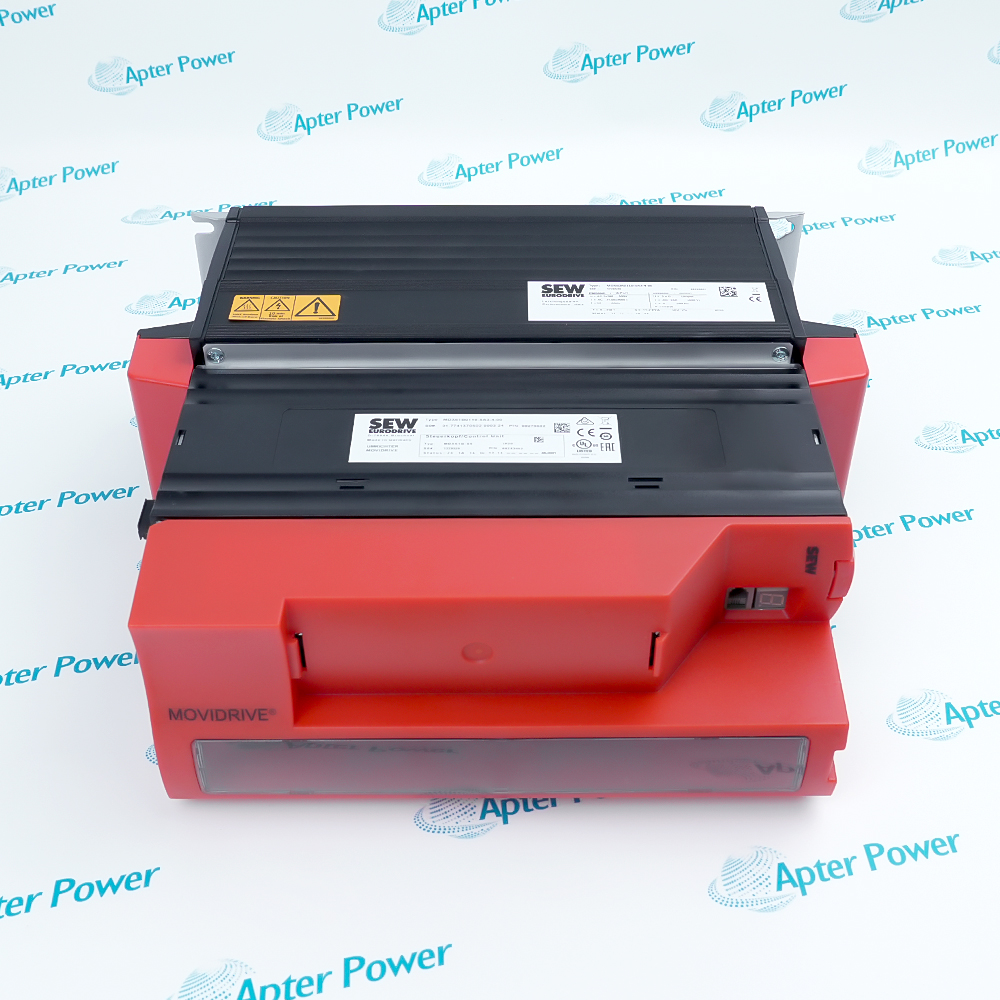
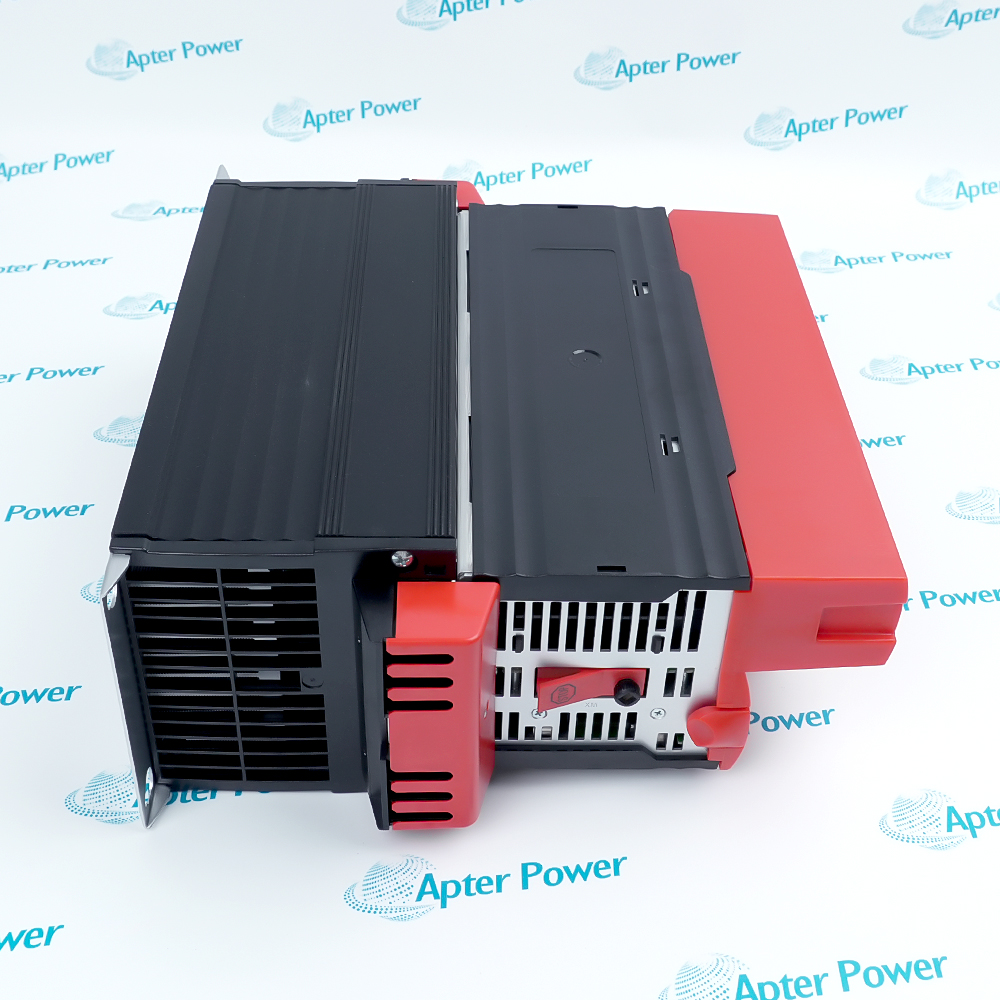
Features:
- Forms the 400/500 V size 2 power stage for compatible MOVIDRIVE MD_60A drive configurations.
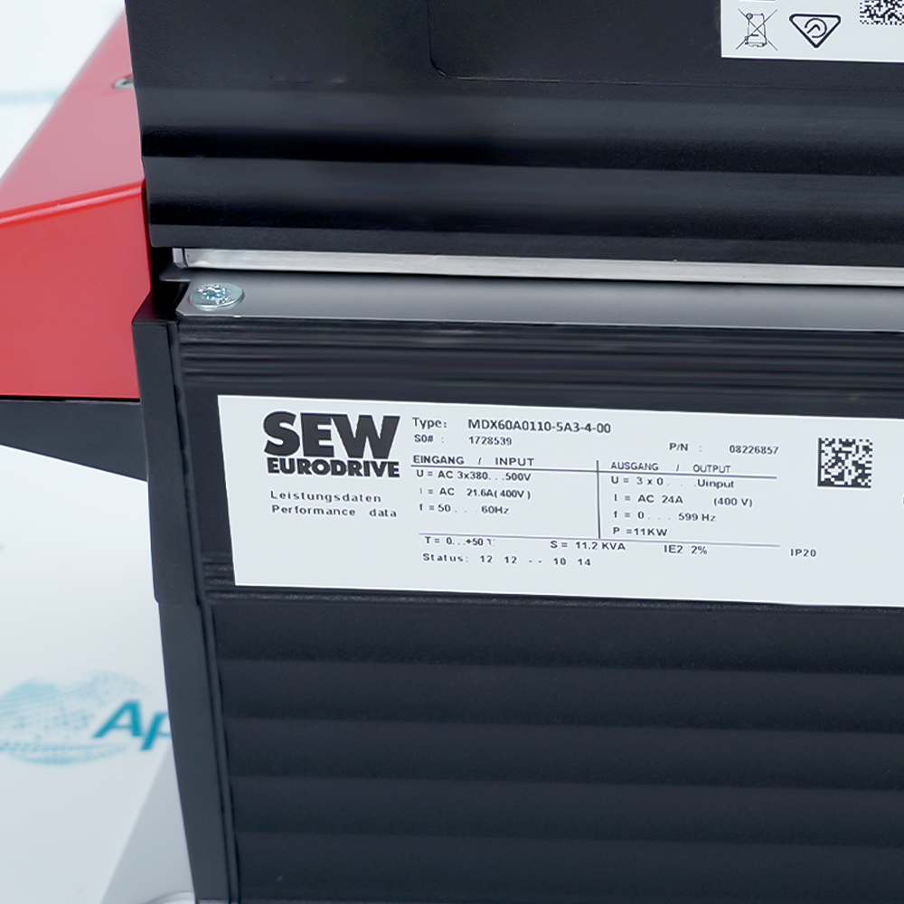
- Delivers 16.8 kVA and 24 A from a three-phase 380–500 V AC supply.
- Requires vertical installation with 100 mm cooling clearance above and below.
SEW-EURODRIVE MDX60A0110-5A3-4-00 handles motor power conversion, while the selected MDF60A, MDV60A, or MDS60A execution determines the complete control function.
The operating mode governs the permitted PWM arrangement, linking VFC, CFC, or SERVO control to the switching frequency used by the power stage.
Losses and airflow define the cabinet boundary: the 400 W thermal load must be removed through the documented vertical cooling path.
The SEW-EURODRIVE MDX60A0110-5A3-4-00 MOVIDRIVE MD_60A Power Section may still be available for purchase and support from Apter Power beyond End-Of-Life (EOL) by the manufacturer (OEM).
SEW-EURODRIVE MDX60A0110-5A3-4-00 MOVIDRIVE MD_60A Power Section Manuals,Datasheets,Link
Important Notice: Other accessories, manuals, cables, calibration data, software, etc. are not included with this equipment unless listed in the above stock item description. All prices are shown in USD.
From mains input to the motor terminals
- Supply entry: Three-phase AC enters the power section before the selected control execution determines the output behavior.
- DC-link stage: The incoming energy is conditioned on the common internal link used by the inverter power stage.
- Motor stage: The power semiconductors convert that link energy into the controlled three-phase motor output.
- Configuration boundary: The power section supplies energy conversion, but MDF60A, MDV60A, or MDS60A defines the complete control function.
Why switching frequency follows the control method
- VFC operation: Several carrier choices allow the switching pattern to be selected within the VFC operating method.
- CFC operation: CFC fixes the carrier at the documented 8 kHz setting rather than using the full VFC list.
- SERVO operation: SERVO uses the same 8 kHz carrier boundary as CFC for this power section.
- Commissioning check: The configured carrier must therefore be reviewed together with the active control execution and not as an isolated parameter.
Moving heat out of the power section
- Loss source: Semiconductor switching and current flow create the documented thermal load inside the size 2 enclosure.
- Air route: Forced cooling must pass vertically through the heatsink path instead of being trapped by adjacent equipment.
- Clearance role: Free space above and below provides the inlet and outlet area needed by that air route.
- Cabinet result: The airflow and spacing are cabinet-design conditions, not optional improvements to the electrical rating.
Keeping power, motor, and braking paths separate
- Mains path: Incoming conductors feed the power section within the documented three-phase voltage range.
- Motor path: Output conductors carry the controlled waveform to the selected motor and must remain separate from control wiring.
- Brake path: The braking resistor connects to its designated circuit and must respect the minimum resistance boundary.
- Protective path: Grounding and vertical installation complete the enclosure and heat-dissipation arrangement described for the unit.