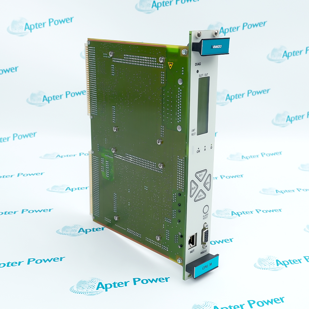
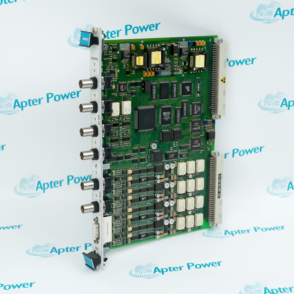
Features:
- Catalog configuration: UVC752 with part number 204-752-000-014.
- Rack context: the installed slot, connector arrangement, and channel schedule define the service configuration.
- Variant boundary: electrical and channel values must come from documentation for this configuration.
UVC752 204-752-000-014 is presented as an exact catalog configuration rather than a generic UVC752 family page.
Selection should be based on the full label and the installed rack documentation.
Commissioning should confirm connector seating, channel response, and normal system diagnostics.
For Vibro-Meter UVC752 204-752-000-014 Vibration Monitoring Module, Apter Power supports quotations, technical documents, and installed-system configuration checks.
Vibro-Meter UVC752 204-752-000-014 Vibration Monitoring Module Manuals,Datasheets,Link
Important Notice: Verify the complete catalog number, document revision, and installed-system configuration before use.
- The installed slot and edge connector define the module interface within the vibration-monitoring rack.
- Confirm connector orientation and seating before power is applied.
- Use the rack wiring and channel schedule to trace each signal path.
- Compare slot width, front-panel clearance, and connector geometry before installation.
- Preserve adjacent-module positions and cable routing during cabinet work.
- Apply the rack isolation and power-up sequence specified for the installed system.
- Inspect connector seating and cable condition before power is applied.
- Confirm channel response against the site baseline.
- Check system diagnostics and alarm behavior before return to service.
- Maintenance of installed Vibro-Meter vibration-monitoring racks.
- Exact-configuration service where 204-752-000-014 is documented.
- Industrial machinery-monitoring systems with verified rack drawings and channel schedules.


 Browse Vibro-Meter products