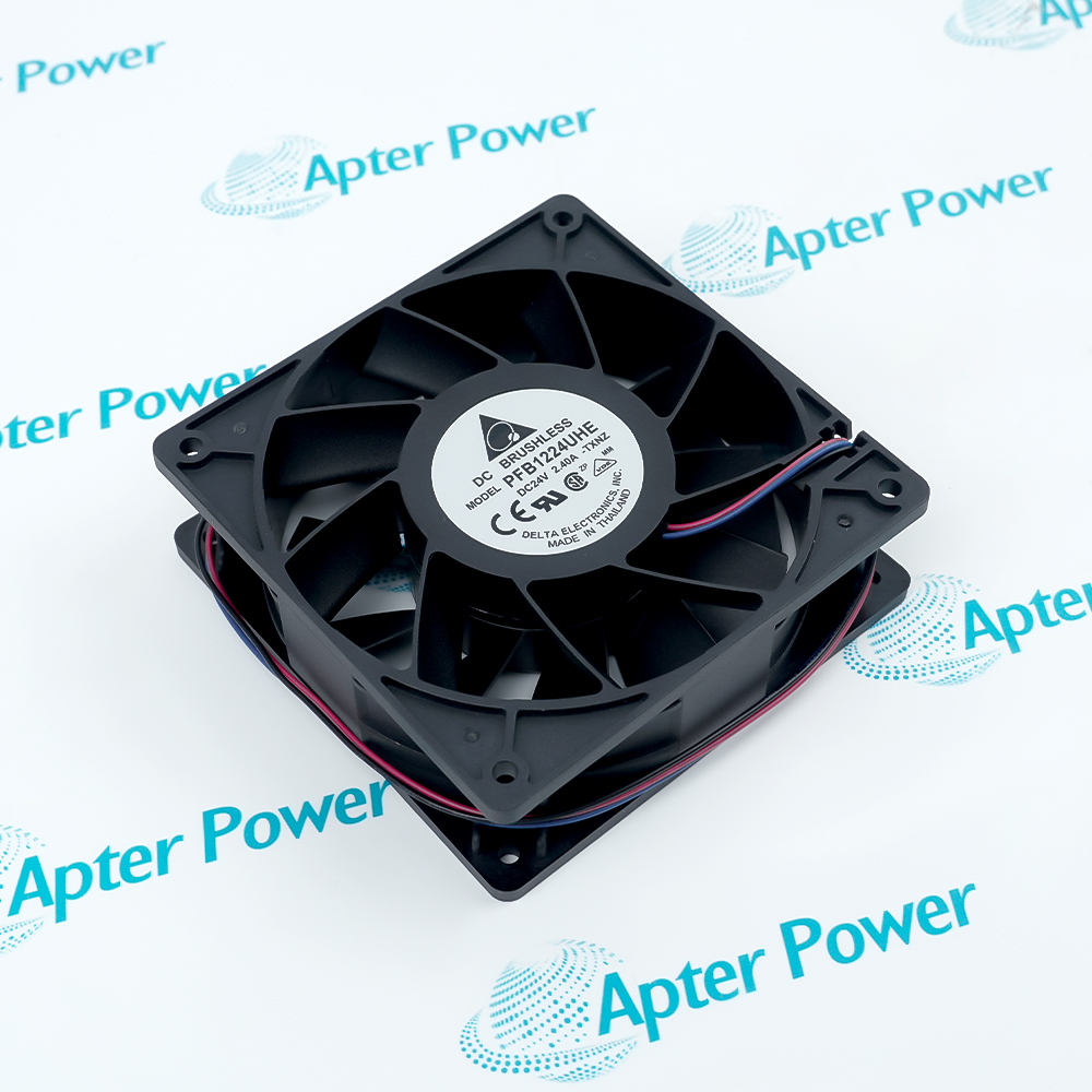
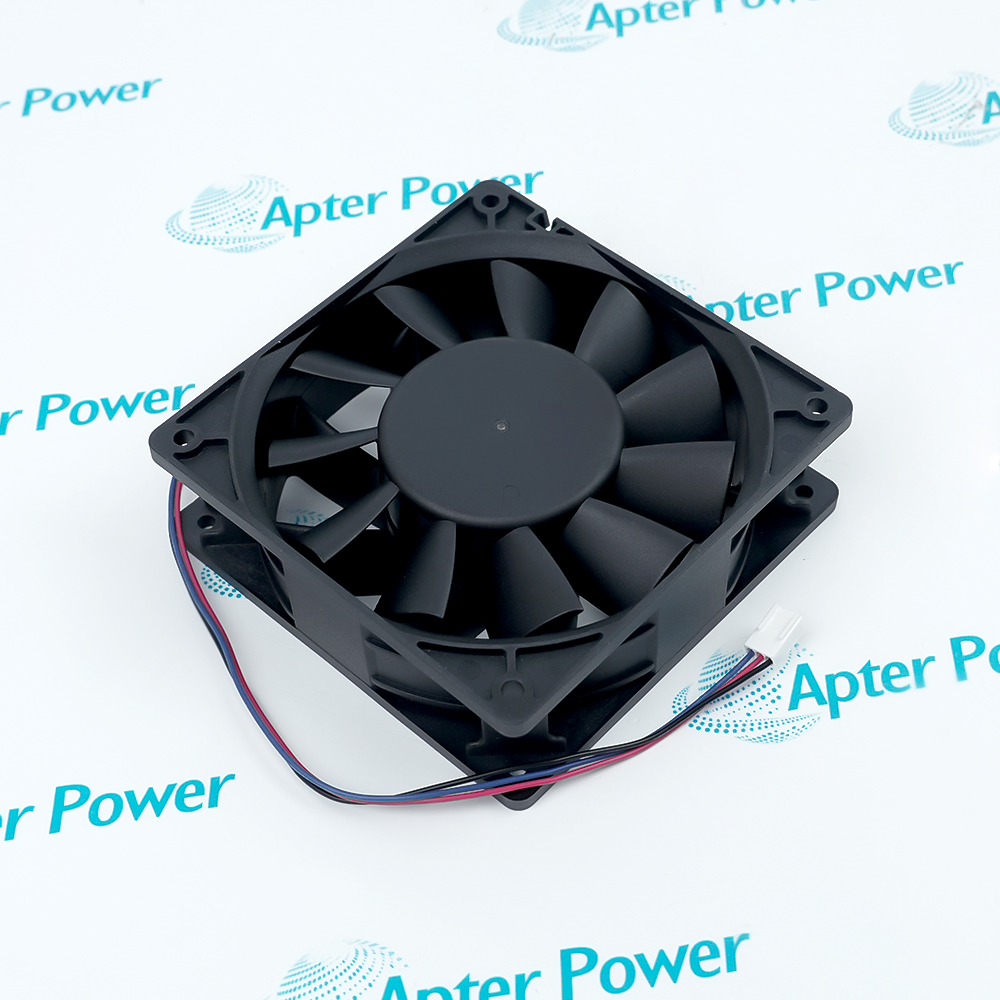
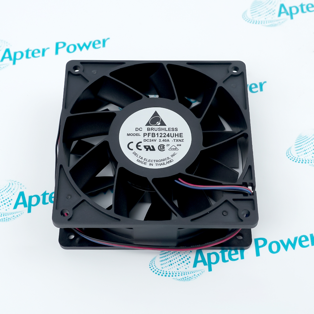
Features:
- Moves at least 252.85 CFM through a 120 mm square frame at the rated operating point.
- Runs from a protected 24 V DC brushless motor with red and black AWG 24 leads.
- Uses two ball bearings and clockwise nameplate-side rotation for the documented service-life rating.
Delta Electronics PFB1224UHE places its motor and impeller inside a 38 mm-deep open fan frame.
The operating point links airflow, static pressure, speed and electrical loading rather than presenting those values as unrelated limits.
Locked-rotor and polarity protection act on the power path while the bearing system supports continuous rotation.
The Delta Electronics PFB1224UHE 120 mm DC Brushless Axial Fan is available for quotation, manual support, and product selection through Apter Power.
Delta Electronics PFB1224UHE DC Brushless Axial Fan Manuals,Datasheets,Link
Important Notice: Other accessories, manuals, cables, calibration data, software, etc. are not included with this equipment unless listed in the above stock item description. All prices are shown in USD.
How Air Moves Through the Fan
- Axial route: Air enters and leaves along the fan axis rather than turning through a centrifugal housing.
- Impeller reference: The impeller rotates clockwise when PFB1224UHE is viewed from the nameplate side.
- System resistance: The delivered airflow follows the pressure-versus-airflow curve as guards, filters or ducts add resistance.
- Frame boundary: The 120 mm square opening and 38 mm depth define the mechanical airflow passage through the equipment.
DC Supply and Motor Circuit
- Supply pair: The red AWG 24 lead carries positive DC power and the black lead returns it to the source.
- Permitted input: The brushless drive must remain inside the documented 14–26.5 V DC operating window.
- Load relationship: Motor current and input power increase from their rated values toward the documented maxima as fan load changes.
- Commutation path: The internal electronic drive commutates the brushless motor, so the two external leads provide power rather than phase connections.
Electrical Fault Response
- Blocked impeller: Locked-rotor protection limits the electrical effect of a fan that cannot start or continue turning.
- Reversed leads: Polarity protection prevents a reversed DC connection from being treated as the normal supply direction.
- Insulation check: The specified insulation-resistance test verifies separation between the live motor circuit and the fan frame.
- Dielectric check: The withstand-voltage test applies a separate short-duration stress to that same insulation boundary.
Operating and Life Boundaries
- Powered operation: PFB1224UHE is specified for operation from -10 to 60 °C within the documented humidity range.
- Unpowered storage: The wider -40 to 75 °C range applies while the fan is stored rather than running.
- Moisture limit: Operating and storage humidity limits are non-condensing boundaries for the motor and insulation system.
- Life condition: The 70,000-hour life figure is tied specifically to 40 °C and 15–65% relative humidity.