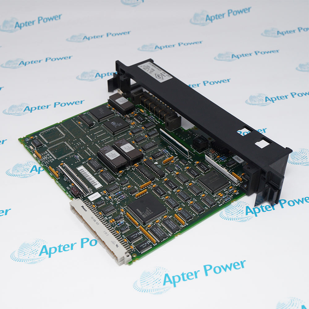
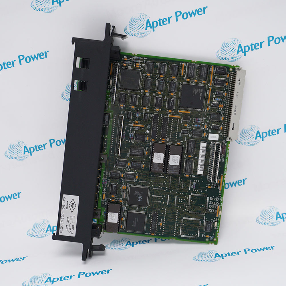
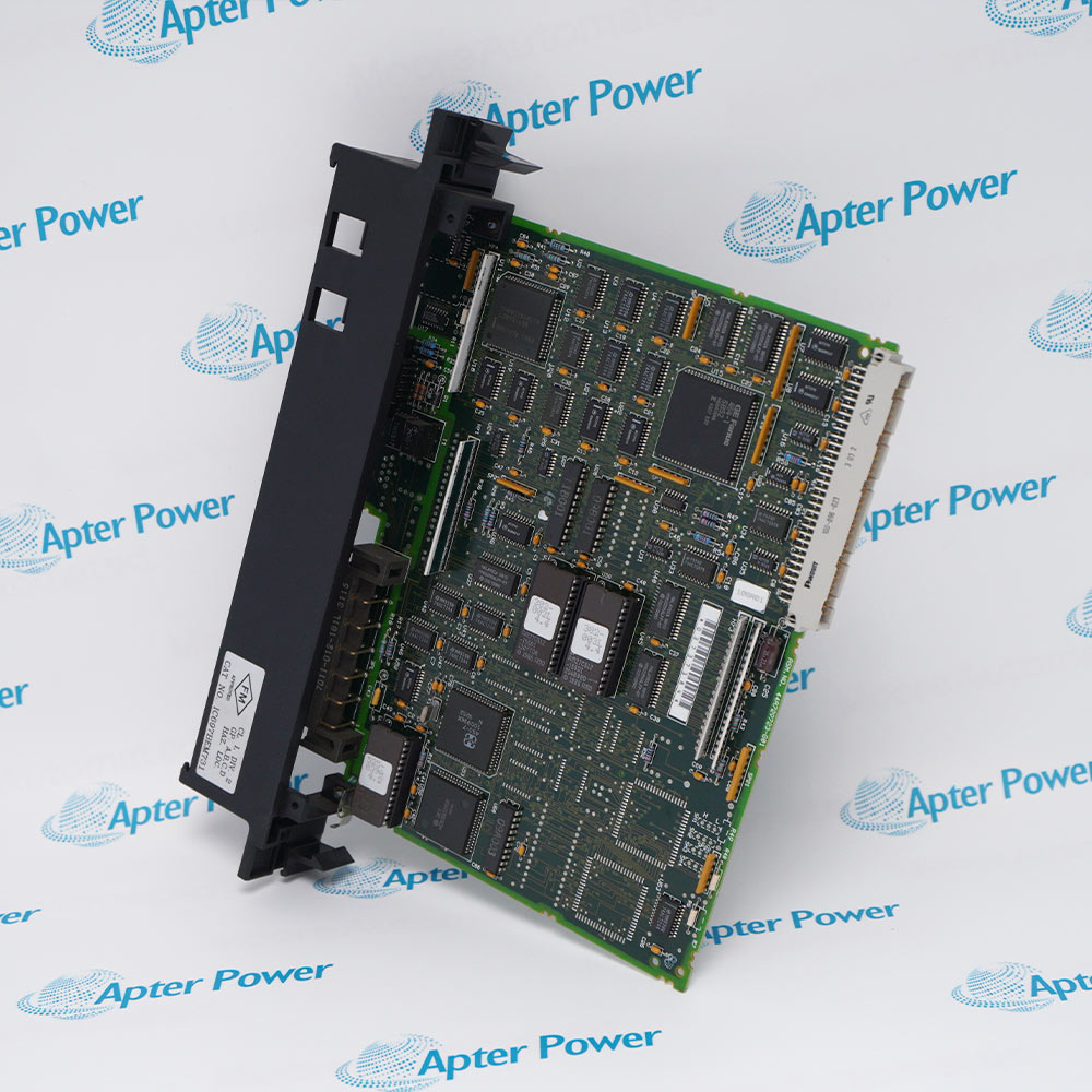
General Electric IC697BEM731
Ask our team:
  • Phone: +86 181 0690 9650
  • E-Mail sales1@apterpower.com
How We Verify Your Order
Before dispatch, we confirm the exact model, revision, condition, inspection requirements and shipping documents for your order.
See a real on-site verification case >>
  • Lifecycle status

    Retired

IC697BEM731

/ 4.9
1001 reviews | Need a Specific Revision?
GE IC697BEM731 links a Series 90-70 rack to one Genius I/O channel for distributed I/O, peer data and redundant-bus configurations.
In Stock
Ships by Saturday, November 14
Fast Shipping Available
Get a quick price for IC697BEM731
Quantity
*E-mail
Company
*Mobile
*Content
Upload (gif, jpg, jpeg, png, bmp, doc, docx, xls, xlsx, ppt, pdf, csv)

Technical specifications for IC697BEM731

  • Manufacturer:
    General Electric
  • Part Number:
    IC697BEM731
  • Product Family:
    GE 90-70 Series PLC
  • Product Type:
    Genius I/O Bus Controller Module
  • Stock:
    1
  • Bus Channels:
    1
  • Maximum Drops:
    30
  • Default Device Address:
    31
  • Baud Rates:
    153.6 K standard/extended, 76.8 K, 38.4 K
  • Maximum Distance:
    2,000–7,500 ft depending on rate and cable
  • Bus Termination:
    75, 100, 120 or 150 Ω matched to cable
  • Communications:
    Global data, datagrams and directed requests
  • Redundancy:
    Blocks, cables and CPUs supported
  • Configuration:
    Software configured
  • Hand-Held Monitor:
    Dedicated port
  • Backplane Demand:
    1.3 A at 5 VDC
  • Slot Use:
    Single slot
  • Backplane Standard:
    VME C.1
  • Dimensions:
    4 × 21.8 × 29.2 cm
  • Weight:
    0.5 kg
  • Tariff Code:
    8538900000
  • Country of origin:
    USA
  • Place of shipment:
    Xiamen, Fujian, China
By purchasing this item, you agree to the Terms & Conditions, ApterPower is not an authorized distributor for listed manufacturers or tradenames and therefore the manufacturer's warranty does not apply. All our products come with ApterPower's 1-year warranty.

More Information

Overview Manuals Bus Migration Redundancy Review Diagnostic Return Application
  • Series 90-70 controller interface for an installed Genius I/O bus
  • Front diagnostics and Hand-Held Monitor connection support bus servicing
  • Bus address, baud rate, termination and field wiring must be preserved

IC697BEM731 connects a Series 90-70 PLC rack to an installed Genius I/O bus and manages communication with the devices assigned to that bus.

Replacement selection must use the complete catalog number, hardware revision, rack assignment and Genius bus connection arrangement rather than the appearance of the front panel alone.

Before removal, record the bus configuration, identify incoming and outgoing wiring, confirm termination and retain the PLC hardware configuration for post-installation diagnostics.

Availability, condition, price, and shipping time for IC697BEM731 are confirmed during quotation.

GE IC697BEM731 Genius I/O Bus Controller Module Manuals, Datasheets, Links

Important Notice: Other accessories, manuals, cables, calibration data, software, etc. are not included with this equipment unless listed in the above stock item description. All prices are shown in USD.

  • Export the complete Genius device and reference map
  • Record controller address, baud rate and cable type
  • Photograph terminal polarity, shields and end termination
  • Identify single or dual bus topology
  • Confirm block and CPU redundancy dependencies
  • Prove the controlled switchover path after service
  • Compare active-device count with the baseline
  • Review bus scan time and PLC fault entries
  • Exercise global data and selected field I/O
  • Distributed Genius I/O control
  • Peer and global-data exchange on a Genius bus
  • Redundant Genius cable or CPU architectures
Description
IC697BEM731 controls one Genius I/O channel with as many as thirty drops. The module supports redundant blocks, dual bus paths and peer communications when the surrounding system is engineered for those modes.

Bus address, baud rate, cable type and termination are system-wide settings. A mismatch at one controller can prevent the entire channel from communicating.

Before replacement, record the device number, reference mapping, global-data configuration, cable impedance and the status of every bus device. Commission by comparing the live bus map and PLC fault table.
Revisions

Revision Part #

Also known as

IC697BEM731C
IC697BEM731-C, Series C, Rev C
IC697BEM731F
IC697BEM731-F, Series F, Rev F
IC697BEM731M
IC697BEM731-M, Series M, Rev M
Alternative Names
IC697BEM731 GBC IC 697 BEM 731 GE Fanuc IC697BEM731 GE IC697BEM731 General Electric IC 697 BEM 731 General Electric IC697BEM731
Technical notes
Before returning GE IC697BEM731 to automatic control, verify every active Genius bus device, bus scan time, global-data exchange, redundancy switchover if used, alarm-processor entries, and controlled I/O operation.
Exceptional Service

Our Mission

  • 100% Satisfaction

    We believe expertise is priceless. With over 20 years of experience, and top engineers on staff, we can help you solve or avoid problems that threaten your business.
  • Trust Guaranteed

    Not only do we have a vast inventory, our team makes sure every piece of equipment is in working condition. Your purchases are also backed by our Warranty.
  • Expertise

    Time is money, especially when your equipment is down. We work quickly to get your equipment on its way so you can get it back up and running.

FAQS

The following is a list of questions commonly asked by our customers. Please contact us if you have a question about our process that is not answered below.
What must match before GE IC697BEM731 is approved as a replacement?
Confirm hardware revision, firmware, device address, baud rate, slot, global-data layout, bus redundancy mode and the exact terminal and cable arrangement.
Why can a Genius channel fail after installing GE IC697BEM731 even when the LEDs look normal?
A mismatched baud rate, duplicate device address, incorrect termination, reversed Serial 1/Serial 2 conductors or broken shield path can block communications without obvious hardware damage.
How should bus termination be selected for GE IC697BEM731?
Use a resistor matching the installed cable impedance at both physical ends of the electrical bus. Do not choose 75, 100, 120 or 150 ohms by module preference.
Can GE IC697BEM731 be substituted with an earlier hardware revision?
Only after checking CPU, block and software compatibility. Later applications may require a minimum controller hardware or firmware level that an earlier spare does not meet.
What data should be archived before changing GE IC697BEM731?
Save the PLC project, bus device map, reference addresses, global-data definitions, datagram logic, fault table, device numbers and cable/termination drawings.
Does GE IC697BEM731 include the removable terminal assembly and terminator?
Do not assume so. Confirm the quotation and photographs for the terminal block, mating plug and end-of-bus resistor before scheduling the outage.
How should GE IC697BEM731 be tested after commissioning?
Verify every active device, bus scan time, global-data exchange, redundancy switchover if used, alarm-processor entries and controlled I/O operation before restoring automatic control.