Ask our team:
  • Phone: +86 181 0690 9650
  • E-Mail sales1@apterpower.com
  • Lifecycle status

    Discontinued / Obsolete by OEM
    Apter Power can review DS200TCDAH1B pricing and direct customers to official General Electric digital I/O documentation for maintenance planning.

DS200TCDAH1B

/ 4.9
1001 reviews | Need a Specific Revision?
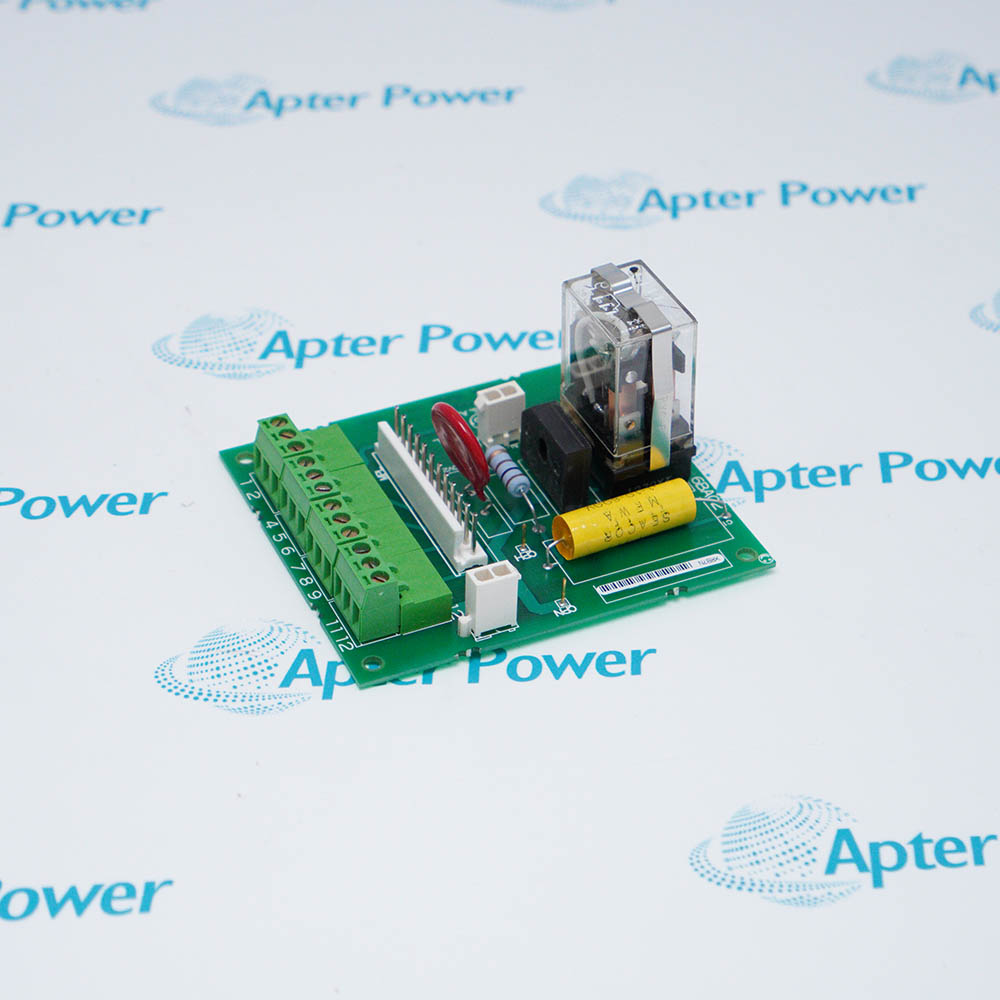
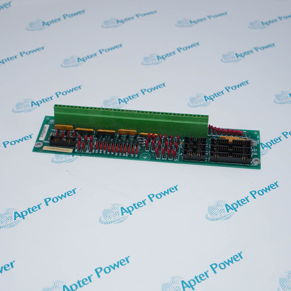
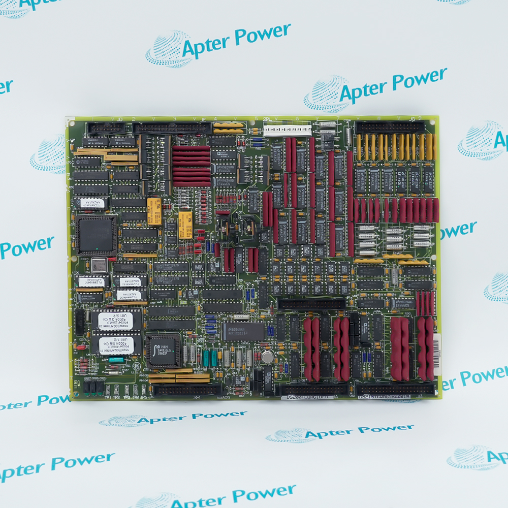
DS200TCDAH1B is a General Electric Mark V digital input/output board that processes contact inputs and relay outputs within the QD core.
In Stock
Ships by Thursday, October 29
Fast Shipping Available
Get a quick price for DS200TCDAH1B
Quantity
*E-mail
Company
*Mobile
*Content
Upload (gif, jpg, jpeg, png, bmp, doc, docx, xls, xlsx, ppt, pdf, csv)

Technical specifications for DS200TCDAH1B

  • Manufacturer:
    General Electric
  • Part Number:
    DS200TCDAH1B
  • Product Family:
    GE Mark V/VI Driver Board
  • Product Type:
    Mark V digital input/output board
  • Stock:
    1
  • Functional acronym:
    TCDA
  • System platform:
    SPEEDTRONIC Mark V
  • Core positions:
    Q11, Q21, or Q51
  • Signal role:
    Contact input and relay-output processing
  • Processor:
    Onboard microprocessor
  • Firmware storage:
    Socketed PROM modules
  • Contact-input interfaces:
    JQ from DTBA; JR from DTBB
  • Contact-output interfaces:
    JO1 and JO2 to TCRA boards
  • Network connectors:
    JX1 and JX2 IONET daisy chain
  • Power connector:
    JP from TCPS
  • Hardware jumpers:
    8
  • Status indicators:
    One side LED plus a 10-LED block
  • PCB protection:
    Conformal coating
  • Tariff Code:
    8538900000
  • Country of origin:
    USA
  • Place of shipment:
    Xiamen,Fujian,China
By purchasing this item, you agree to the Terms & Conditions, ApterPower is not an authorized distributor for listed manufacturers or tradenames and therefore the manufacturer's warranty does not apply. All our products come with ApterPower's 1-year warranty.

More Information

Overview Manuals I/O Routing IONET Setup Commissioning Diagnostics

Features:

  • Collects contact-input states from DTBA and DTBB terminal boards.
  • Routes relay-output commands through JO1 and JO2 toward TCRA boards.
  • Communicates with the Mark V I/O Engine through a daisy-chained IONET path.
Provides front-visible processing and diagnostic indication for cabinet service.

The General Electric DS200TCDAH1B occupies a digital I/O core rather than a protective overspeed position. Its cable map therefore follows the Q-core drawing and the specific turbine requisition.

A correct General Electric DS200TCDAH1B exchange retains the address and termination settings while keeping factory-test jumpers unchanged.

Contact Apter Power to request current pricing for the General Electric DS200TCDAH1B Mark V digital input/output board.
General Electric DS200TCDAH1B Mark V digital input/output board Manuals, Datasheets, Links Important Notice: Other accessories, manuals, cables, calibration data, software, etc. are not included with this equipment unless listed in the above stock item description. All prices are shown in USD.

Connector-to-function map

  • JQ: Receives contact-input wiring from the DTBA terminal board.
  • JR: Brings the extended input group from the DTBB board.
  • JO1 and JO2: Carry commanded contact outputs toward two TCRA locations.
  • JP: Accepts the power-distribution path from TCPS.
  • JX1 and JX2: Continue the IONET daisy chain through the digital core.

Network hardware choices

  • Termination: Jumpers J2 and J3 control the required IONET termination resistors.
  • Node identity: Jumpers J4 through J6 establish the TCDA node identity.
  • Stall timer: J7 controls the approved stall-timer behavior for the installed design.
  • Test positions: Factory-test positions must remain in their required factory state.
  • Daisy-chain seating: Both daisy-chain plugs must be fully seated before the core is powered.

Return-to-service sequence

  • Core position: Confirm that the board is installed in the same Q-core position as the removed unit.
  • PROM and jumpers: Compare every PROM label and hardware jumper with the saved record.
  • Connector seating: Check JQ, JR, JO1, and JO2 for correct keying and even insertion.
  • Status indication: Observe the side LED for power and processor activity after startup.
  • Contact validation: Use Mark V diagnostics to compare contact states with field conditions.

Separating board, cable, and field faults

  • Input group missing: Trace the affected JQ or JR cable and terminal-board supply.
  • Outputs inactive: Follow JO1/JO2 to the correct TCRA location and relay circuit.
  • IONET timeout: Verify termination, node address, and both JX connections.
  • LED dark: Confirm JP power, fuse status upstream, and board seating.
  • Intermittent points: Inspect cable routing, shielding, connector strain, and contamination.
Description
Contact states and relay commands enter the Mark V digital I/O core through the General Electric DS200TCDAH1B Digital Input/Output Board. It receives field contact states from DTBA and DTBB terminal boards and passes commanded relay outputs toward TCRA boards.

An onboard processor and socketed PROMs allow General Electric DS200TCDAH1B to scan the discrete paths while communicating with the I/O Engine over a daisy-chained IONET connection. JQ and JR are the principal 50-pin input interfaces; JO1 and JO2 carry contact-output signals, and JP brings power distribution from the TCPS board.

Eight jumpers on General Electric DS200TCDAH1B control IONET termination, network identity, the stall timer, and factory-test functions. A side-visible green indicator reports board power and processing activity, while the ten-LED block supports diagnosis from the cabinet front.

During an exchange, General Electric DS200TCDAH1B should retain the original PROM set, IONET address, termination choice, and ribbon-cable routing. Keeping input and output cables away from noisy power conductors helps prevent intermittent contact-state faults.
Revisions

Revision Part #

Also known as

DS200TCDAH1B
DS200TCDAH1-B, Series B, Rev B
Alternative Names
DS200 TCDA H1B DS200-TCDA-H1B GE DS200TCDAH1B General Electric DS200TCDAH1B Mark V DS200TCDAH1B TCDA H1B digital I/O board DS200TCDA H1B DS200TCD-AH1B
Technical notes
DS200TCDAH1B service requires the original core location, PROM set, IONET termination and address jumpers, stall-timer choice, and cable routing to be recorded before removal.
Exceptional Service

Our Mission

  • 100% Satisfaction

    We believe expertise is priceless. With over 20 years of experience, and top engineers on staff, we can help you solve or avoid problems that threaten your business.
  • Trust Guaranteed

    Not only do we have a vast inventory, our team makes sure every piece of equipment is in working condition. Your purchases are also backed by our Warranty.
  • Expertise

    Time is money, especially when your equipment is down. We work quickly to get your equipment on its way so you can get it back up and running.

FAQS

The following is a list of questions commonly asked by our customers. Please contact us if you have a question about our process that is not answered below.
Which settings must be recorded before removing DS200TCDAH1B?
Photograph the DS200TCDAH1B ribbon cables and record the PROM labels, IONET address jumpers, termination jumpers, and core position.
Why is the green side LED on DS200TCDAH1B not flashing?
A steady or dark DS200TCDAH1B side LED calls for checks of the JP supply path, board seating, processor activity, and diagnostic records.
What do JQ and JR connect to on DS200TCDAH1B?
The DS200TCDAH1B JQ cable goes to DTBA, while JR receives the additional contact-input path from DTBB.
How should an IONET error after a DS200TCDAH1B replacement be investigated?
Compare DS200TCDAH1B jumpers J2 through J6, inspect JX1/JX2 daisy-chain cables, and confirm the installed core address.
Can the factory-test jumpers on DS200TCDAH1B be changed during field setup?
No. DS200TCDAH1B factory-test positions should remain in their factory-set positions; field work normally concerns termination, address, and approved stall-timer settings.
Why can a relay fail to operate even when DS200TCDAH1B diagnostics are healthy?
Trace the DS200TCDAH1B JO1/JO2 path to the correct TCRA board, then check the relay circuit, field supply, and terminal wiring.
What is the safest way to reconnect DS200TCDAH1B ribbon cables?
Isolate power, verify connector labels and keying, seat each DS200TCDAH1B cable evenly, and preserve the original routing away from interference sources.