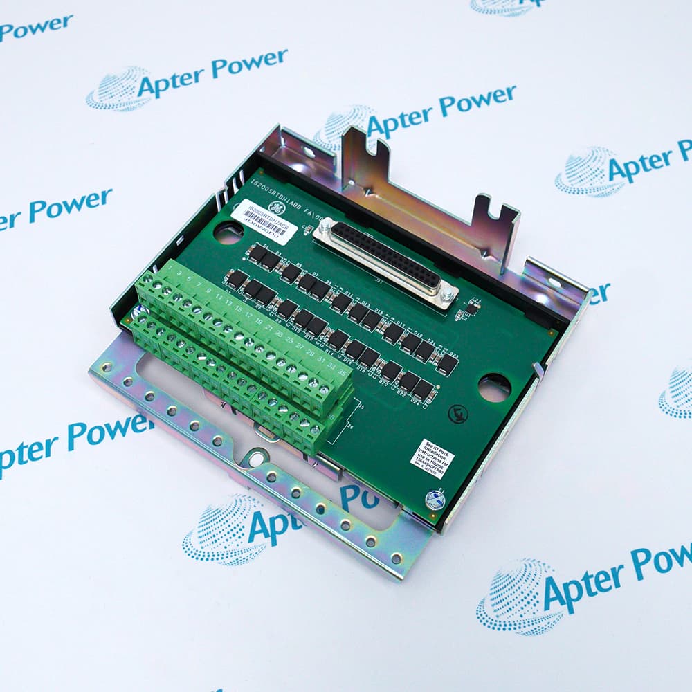
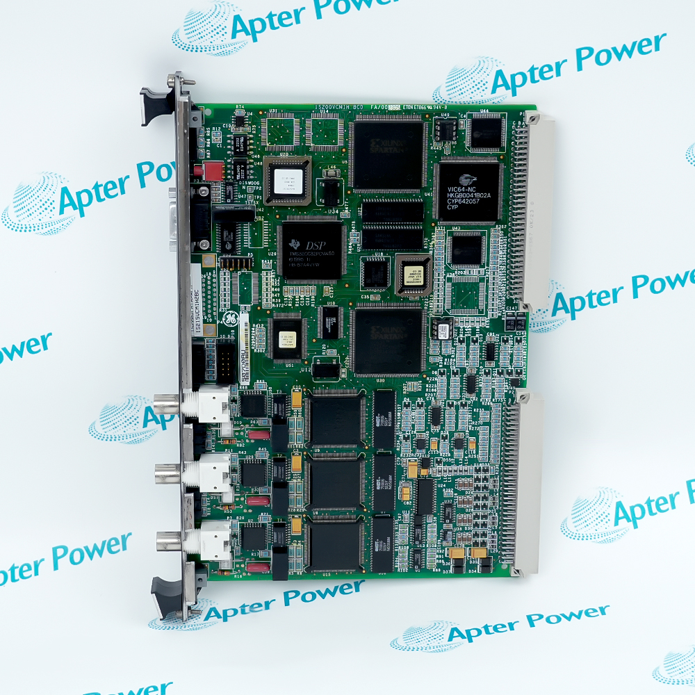
Features:
- Independent emergency overspeed protection
- Triple-redundant VPRO architecture
- H1B support for a second TREG terminal board
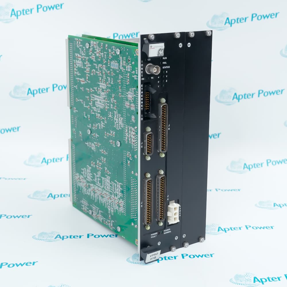
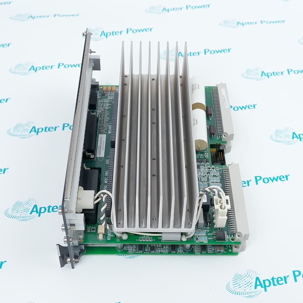
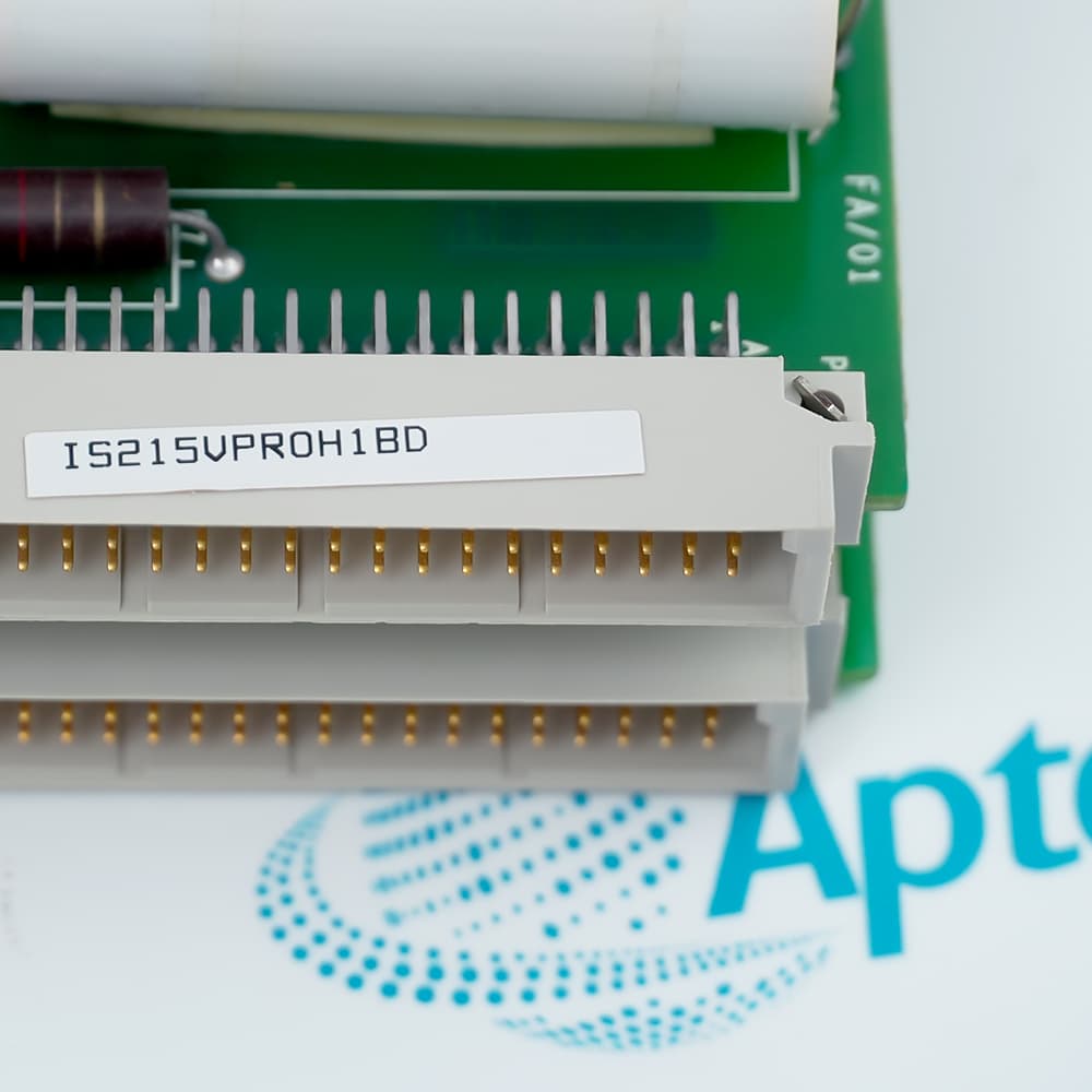
The IS215VPROH1BD ordering code identifies an H1B-form VPRO board for the separate Mark VI Protection Module.
Three VPRO boards operate independently from the turbine control processors and vote on emergency protection conditions before acting on the trip path.
When selecting this code, confirm the installed TPRO, TREG, and TRPG arrangement, especially whether connector J4 serves a second TREG board.
The General Electric IS215VPROH1BD VPRO Emergency Turbine Protection Board is listed as Active / Available from OEM. Apter Power supports official-document review and protection-system matching.
General Electric IS215VPROH1BD VPRO Emergency Turbine Protection Board Manuals, Datasheets, Links
Important Notice: Other accessories, manuals, cables, calibration data, software, etc. are not included with this equipment unless listed in the above stock item description. All prices are shown in USD.
Independent Trip Architecture
- Protection module: Three VPRO boards form a separate triple-redundant emergency protection subsystem.
- Overspeed function: Turbine speed signals are evaluated independently for emergency overspeed conditions.
- Emergency stop: The VPRO logic also processes the emergency-stop path used by the protection module.
- Controller separation: The protection subsystem operates independently from the turbine control processors.
Terminal-Board Roles
- TPRO inputs: Passive magnetic speed pickups and other protection signals enter through the TPRO terminal board.
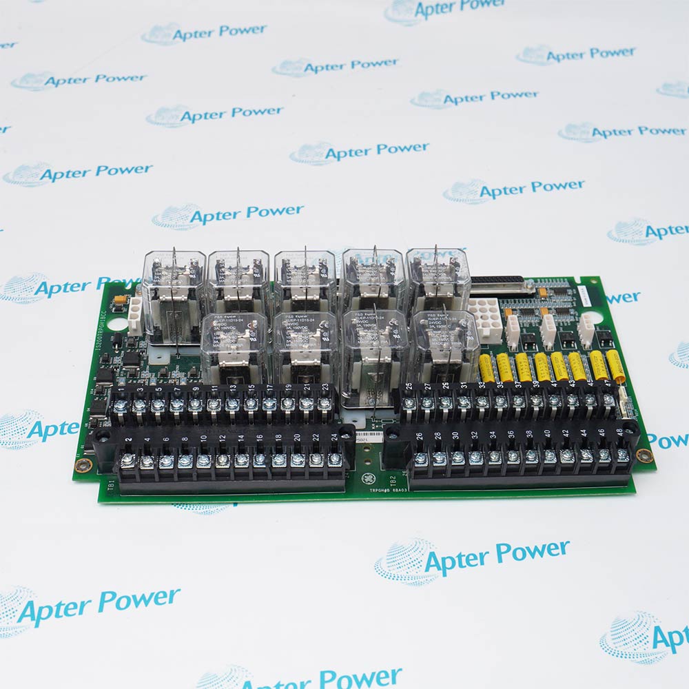
- TREG control: IS215VPROH1BD controls trip relays located on the TREG terminal board.
- Positive feed: TREG supplies the positive side of the trip-solenoid circuit.
- Negative feed: TRPG provides the negative side used to complete the trip-solenoid path.
Front-Panel Interface Map
- J3 path: Retain the documented J3 cable identity and terminal-board destination during replacement.
- J4 path: The H1B configuration uses J4 when a second TREG terminal board is installed.
- J5 and J6: These front connectors must return to their recorded protection-module cable positions.
- J7 power: Verify the board power connection and rack power state before running diagnostics.
Rack Replacement Sequence
- Power removal: De-energize the VME rack under the approved site procedure before removing the VPRO board.
- Board seating: Slide IS215VPROH1BD into the designated slot and use both ejector levers to seat it fully.
- Mechanical security: Tighten the captive screws after the board is aligned and seated in the rack.
- Return to service: Restore J3-J7 cabling, review diagnostics, and complete the approved protection trip-verification process.