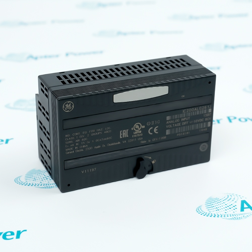
Features:
- Provides four single-ended 12-bit bipolar voltage outputs in one group.
- Separates field-power indication from backplane-power indication for faster fault isolation.
- Uses a hardware selection for hold-last or 0 V behavior during defined interruptions.
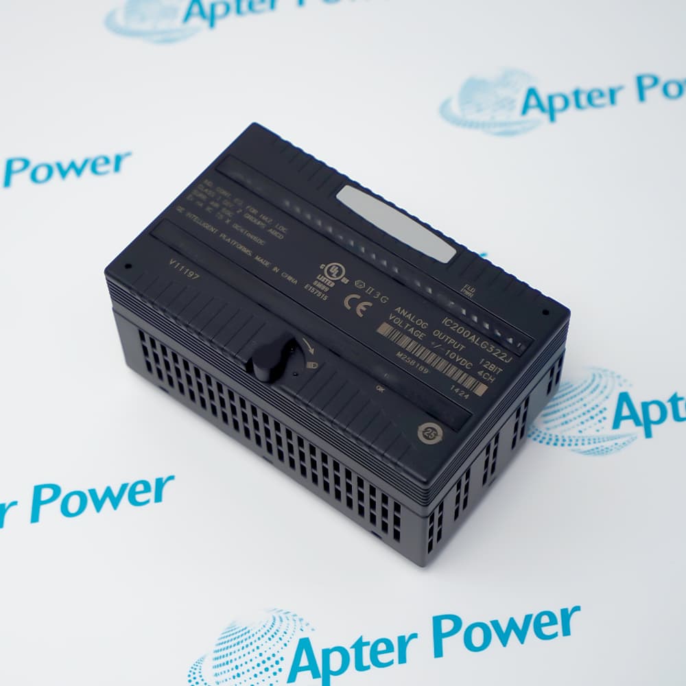
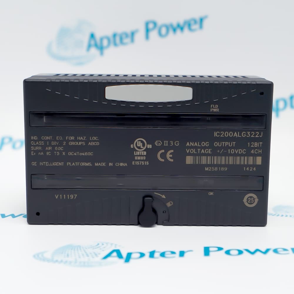
The current ordering configuration is the four-channel VersaMax bipolar voltage output module identified by catalog number IC200ALG322.
It receives four output words from the controller or network interface and converts them into independent analog commands for connected equipment.
Before installation, confirm the carrier type, external supply, channel returns, shield termination and B13-B14 jumper position against the existing wiring drawings.
Availability is subject to Apter Power inventory and sourcing confirmation.
General Electric IC200ALG322 Bipolar Voltage Output Module Manuals,Datasheets,Link
Important Notice: Other accessories, manuals, cables, calibration data, software, etc. are not included with this equipment unless listed in the above stock item description. All prices are shown in USD.
- Supplies bidirectional speed or torque references to equipment designed for bipolar voltage commands.
- Provides positive and negative position references for compatible motion or hydraulic controllers.
- Consolidates four independent analog command loops in a compact VersaMax I/O node.
- An open B13-B14 selection retains the last commanded value when the controller stops or backplane communication is interrupted.
- Installing the B13-B14 jumper changes the defined interruption target for all four channels to 0 V.
- External user power must remain present for either the retained or 0 V response to be maintained.
- Each field circuit uses its numbered voltage-output terminal together with the corresponding return terminal.
- Shielded twisted-pair cable is used between each analog output and the receiving device.
- Shield conductors are terminated through the installed carrier arrangement with the earth connection kept short.
- The FLD PWR indicator confirms the external supply used by the analog field-side circuits.
- The OK indicator confirms that the module is receiving logic power from the VersaMax backplane.
- A reported loss of user-side power directs troubleshooting to the field supply before output-data logic is changed.