Features:
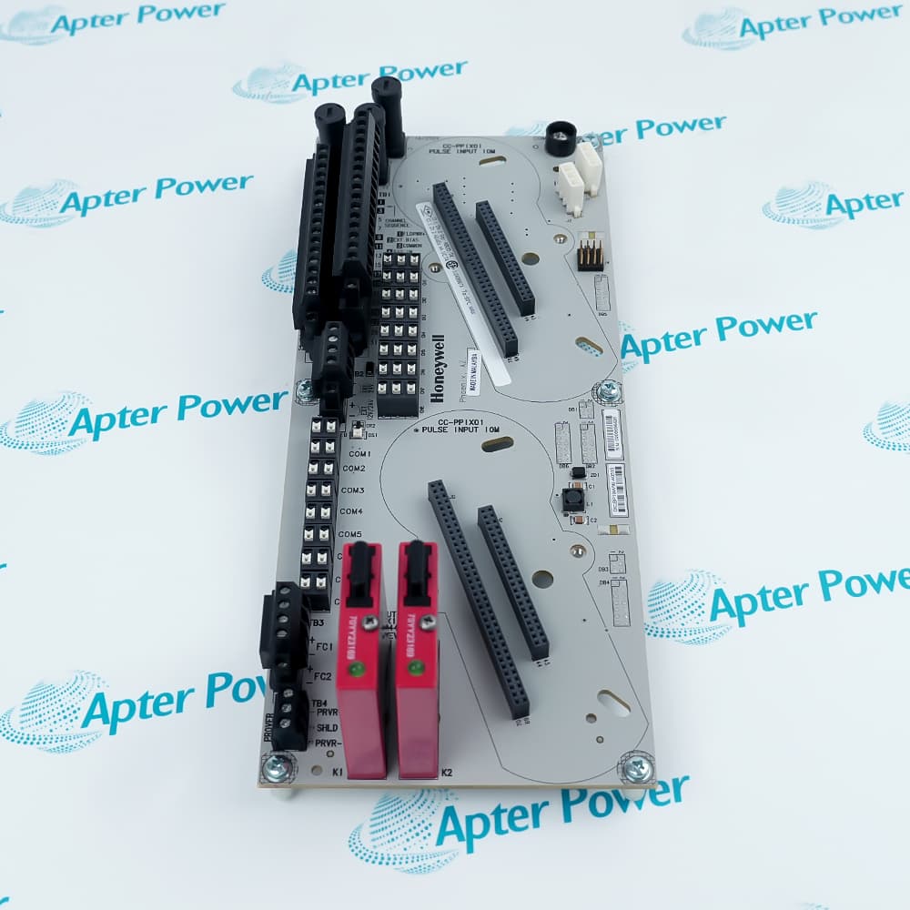
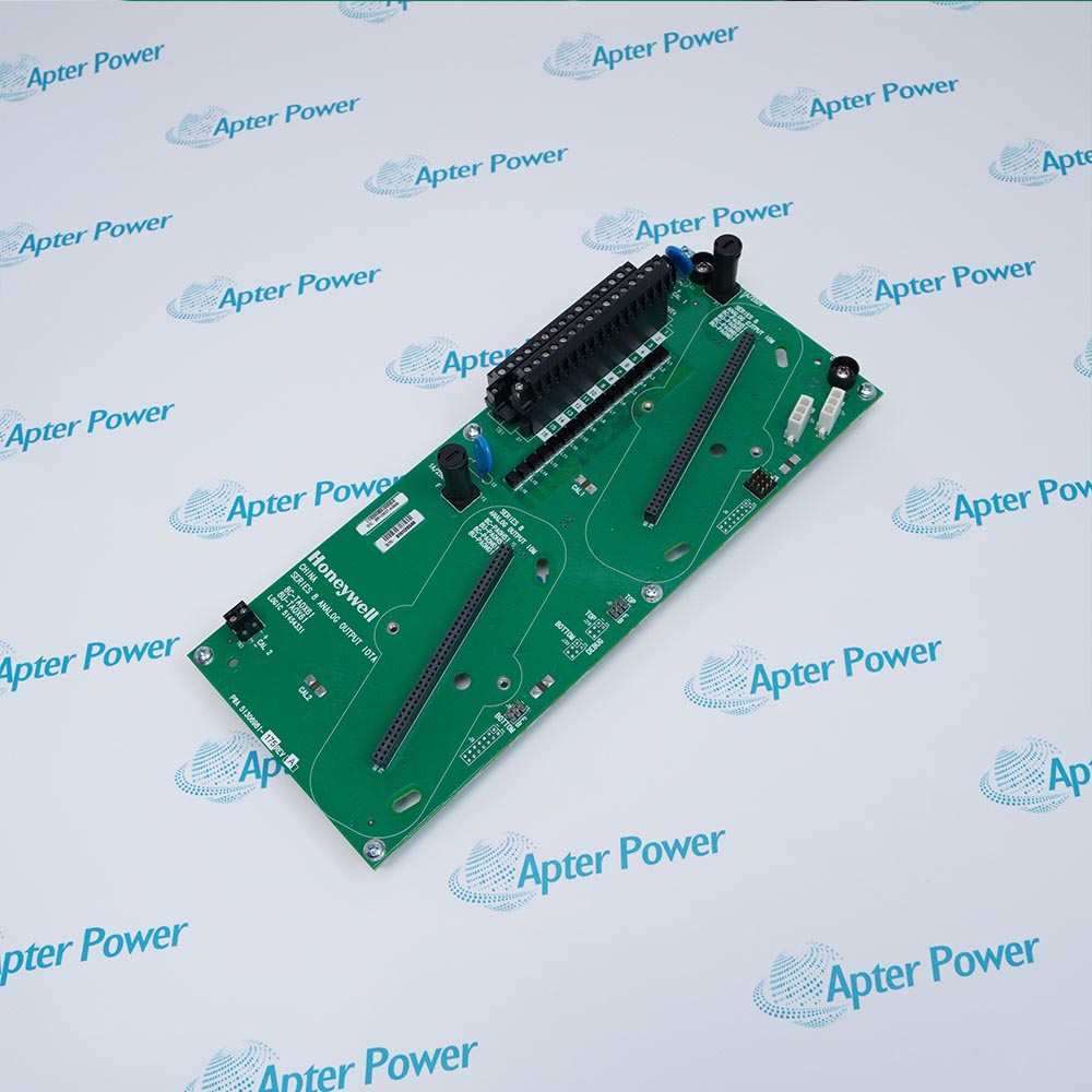
- Provides the redundant 12-inch field-termination layer for the CC-PPIX01 pulse-input path.
- Organizes eight single-pulse inputs, four dual-pulse inputs, or a supported mixed channel plan.
- Lets each channel use isolated or bussed wiring with internal or external excitation.
In Series C I/O, the IOTA keeps field terminations on a separate assembly from the removable pulse-input electronics.
The redundant 12-inch arrangement preserves the documented connection pattern required by the paired pulse-input architecture.
Channel wiring and configuration determine which pulse edges become frequency, accumulated-value, period or pulse-width data.
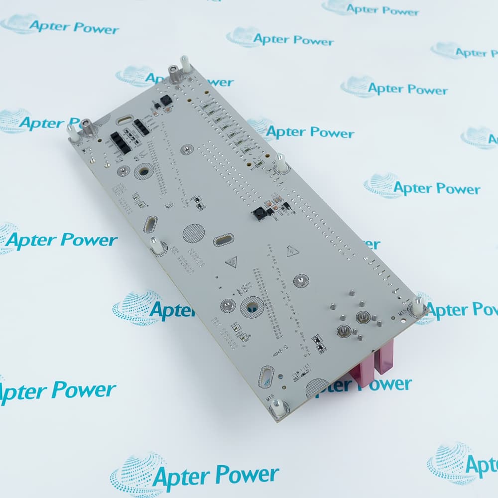
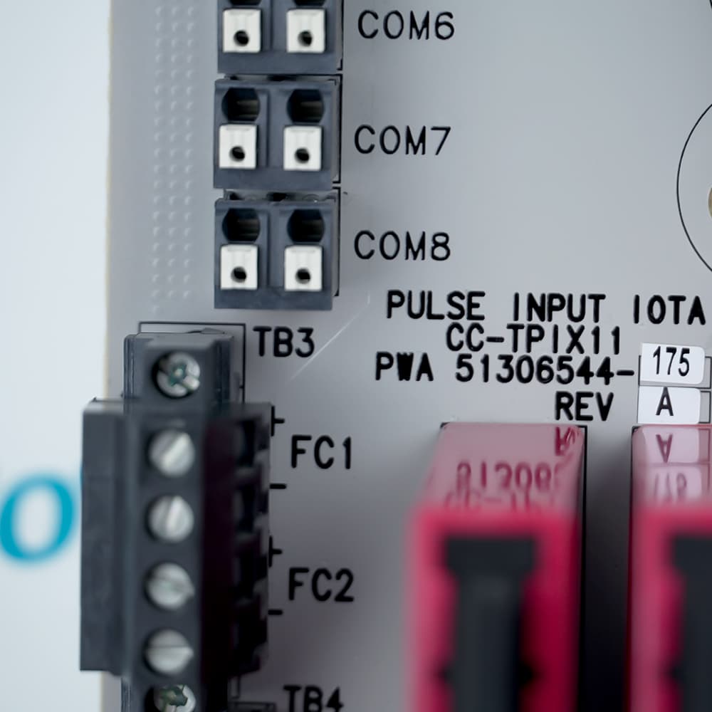
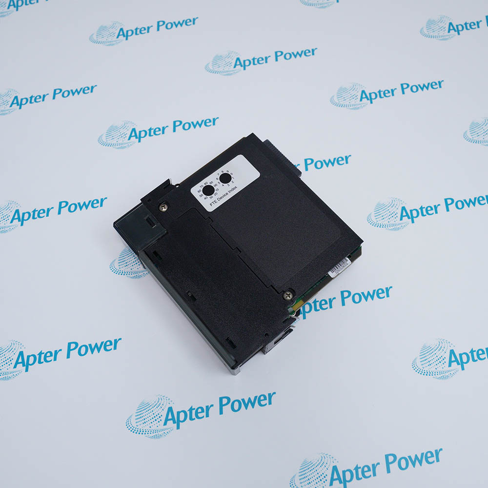
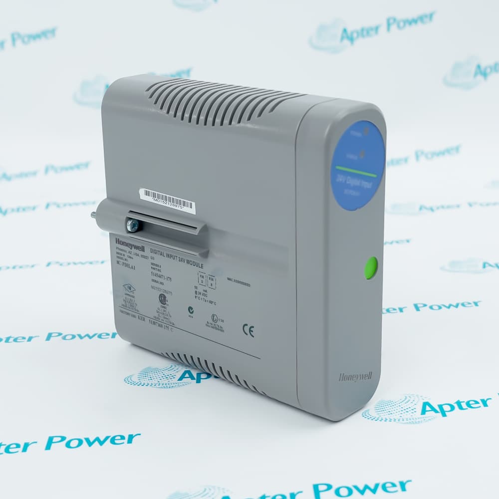
The Honeywell CC-TPIX11 51306544-175 Series C Pulse Input IOTA is covered by current Honeywell Series C I/O documentation and may be available for purchase and support from Apter Power.
Honeywell CC-TPIX11 51306544-175 Series C Redundant Pulse Input IOTA Manuals,Datasheets,Link
Important Notice: Other accessories, manuals, cables, calibration data, software, etc. are not included with this equipment unless listed in the above stock item description. All prices are shown in USD.
Arranging single and paired pulse sources
- Single channels: Eight independent paths accept pulse sources that do not require dual comparison.
- Dual channels: Four paired paths keep the two pulse trains associated for dual-input processing.
- Mixed layout: Single and dual assignments can coexist when the channel plan follows the supported pairing.
- Termination boundary: The IOTA holds the field connections while the CC-PPIX01 provides pulse processing.
Moving a field pulse into the Series C module
- Differential input: Each path receives the voltage difference across its field pair rather than relying on a shared signal lead.
- High impedance: The input presents limited loading to the connected pulse-generating device.
- Edge choice: Configuration selects the rising or falling transition that advances the measurement.
- Optical boundary: Isolation separates the field pulse from the module-side processing circuit.
Turning pulse timing into usable process values
- Frequency: Repeated edges are converted into a rate value for the configured input channel.
- Accumulation: Valid transitions can be totaled to represent the quantity associated with the pulse source.
- Pulse width: High and low intervals remain available as separate timing measurements.
- Period: Time between successive reference edges provides another view of the incoming signal.
Referencing powered and passive pulse devices
- Internal source: The documented 24 V path can energize a compatible field device from the I/O assembly.
- External source: A user-supplied 5–30 V DC source can support devices that need a different excitation arrangement.
- Channel jumper: Isolated or bussed selection defines whether a channel keeps or shares its excitation reference.
- Reference check: Field polarity, return path and selected jumper must agree before the pulse input is commissioned.