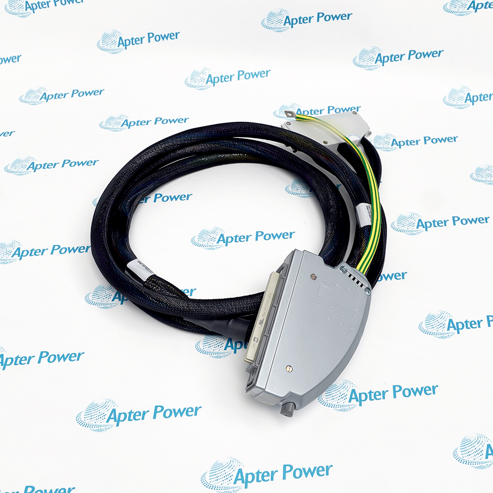
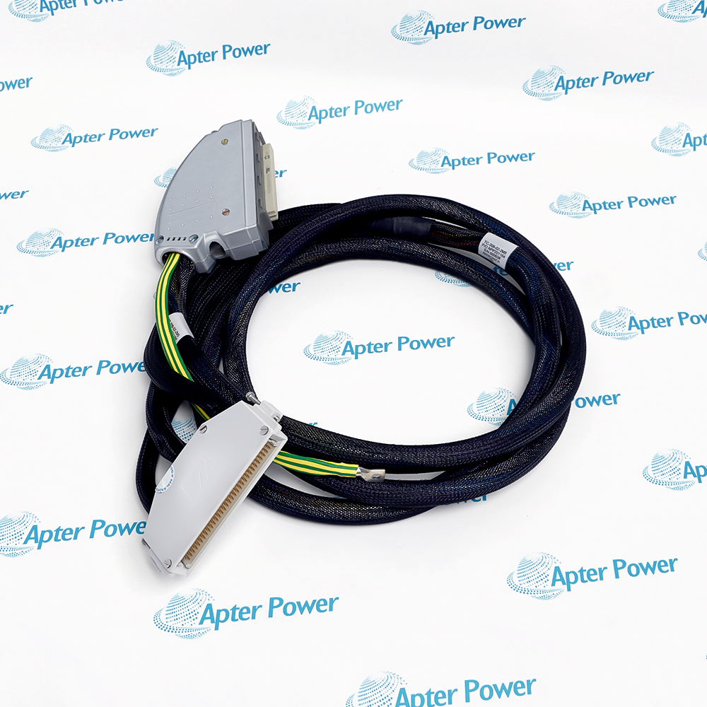
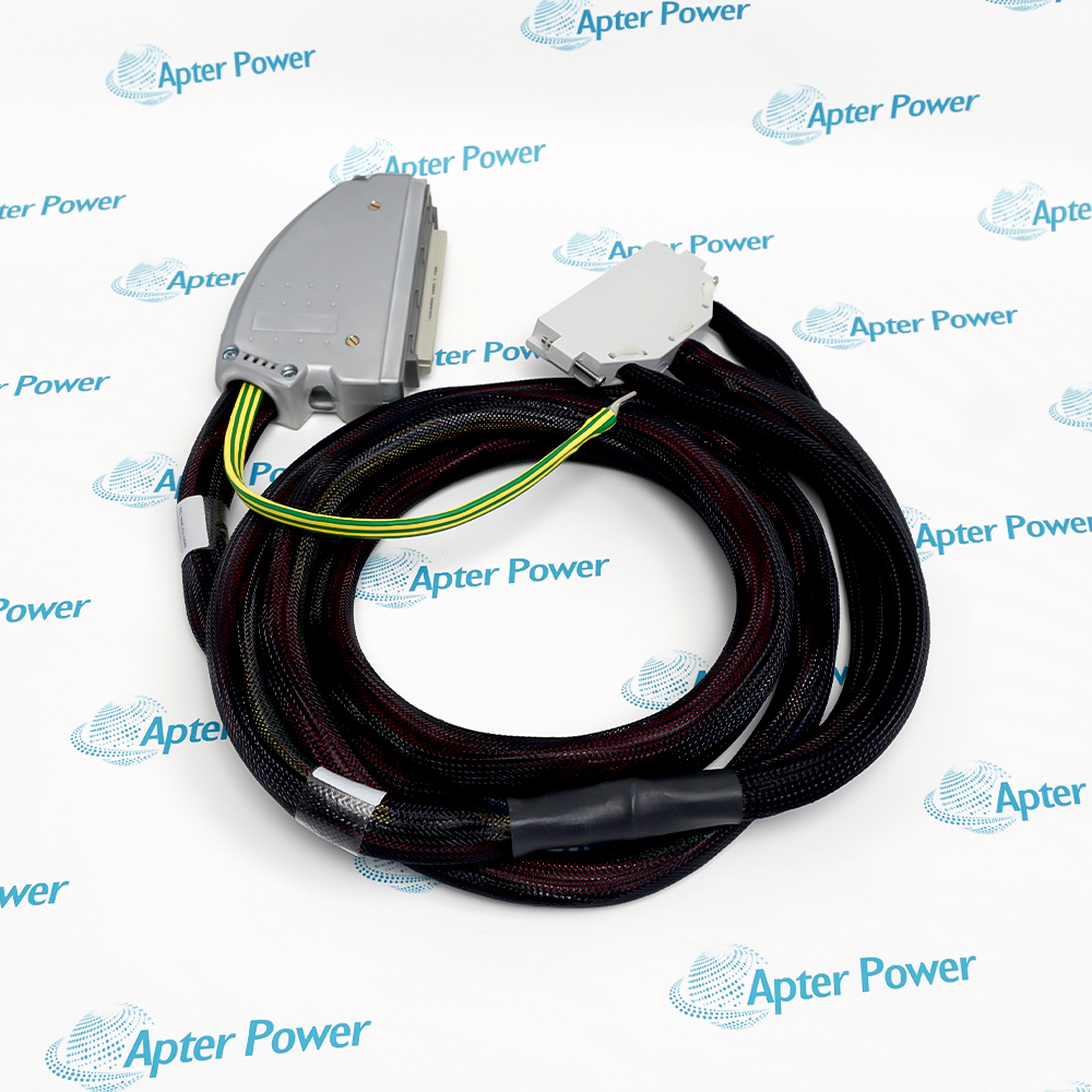
Features:
- A 2.5 m LSZH jumper uses a 96-way harness for Trusted analogue and digital input channels.
- The SmartSlot end has a type C connector, single-width hood and protective earth braid.
- The field-position end terminates in a type R connector with a special-to-type plastic hood.
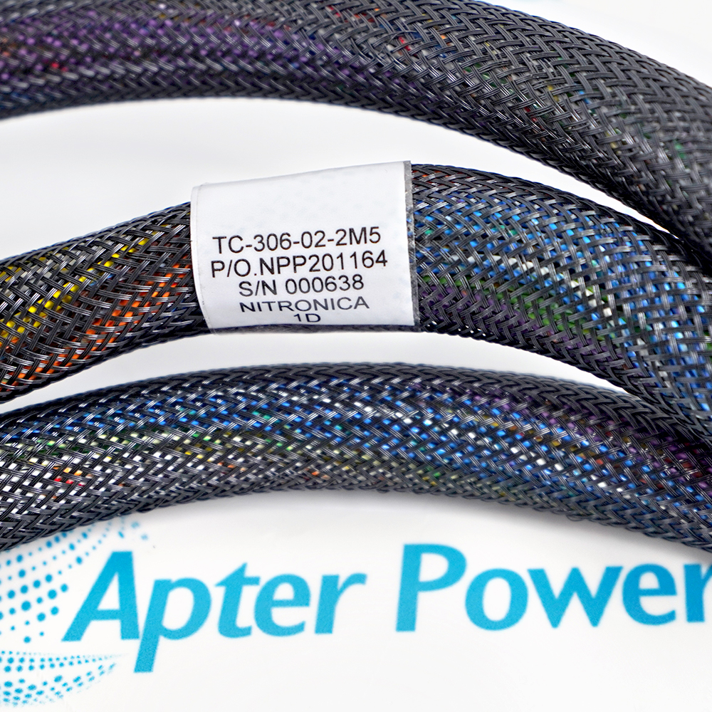
The current ordering configuration is ICS Triplex TC-306-02-2M5, the 2.5 m input SmartSlot jumper with Megamide sleeving and heat-shrink finished cable ends.
It preserves the input signal path when a compatible 40- or 60-channel module is transferred to the SmartSlot in a Trusted Controller or Expander chassis.
Match the input-module direction, 96-way connector keying and same-bay cable route, then test the complete jumper before returning the system to service.
Availability is confirmed against the exact TC-306-02-2M5 label and required quantity.
Verified resources for ICS Triplex TC-306-02-2M5:
Important Notice: Other accessories, manuals, cables, calibration data, software, etc. are not included with this equipment unless listed in the above stock item description. All prices are shown in USD.
- Maintains field connectivity when a supported input module is moved from its normal slot to the chassis SmartSlot.
- Supports planned recovery work on Trusted analogue or digital input positions within the same equipment bay.
- Provides a controlled temporary signal route while the original module position is investigated or serviced.
- Designed for Trusted 40- or 60-channel analogue and digital input module SmartSlot arrangements.
- The installation must match the documented 96-way type C and type R connector orientation.
- Output-module and 120 V jumper variants use different assignments and must not be substituted.
- The 2.5 m reach is intended for routing within one cabinet bay rather than between separate bays.
- Megamide sleeving and heat-shrink ends should remain undamaged and clear of sharp edges or hot surfaces.
- Connector latches, earth braid and cable support should be checked before the chassis is energized.
- The complete jumper and every affected signal path must be tested before operational use.
- Protective earthing continuity must be maintained through the fitted braid and cabinet bonding arrangement.
- Process hazards and module power must be controlled under the site procedure before either connector is disturbed.