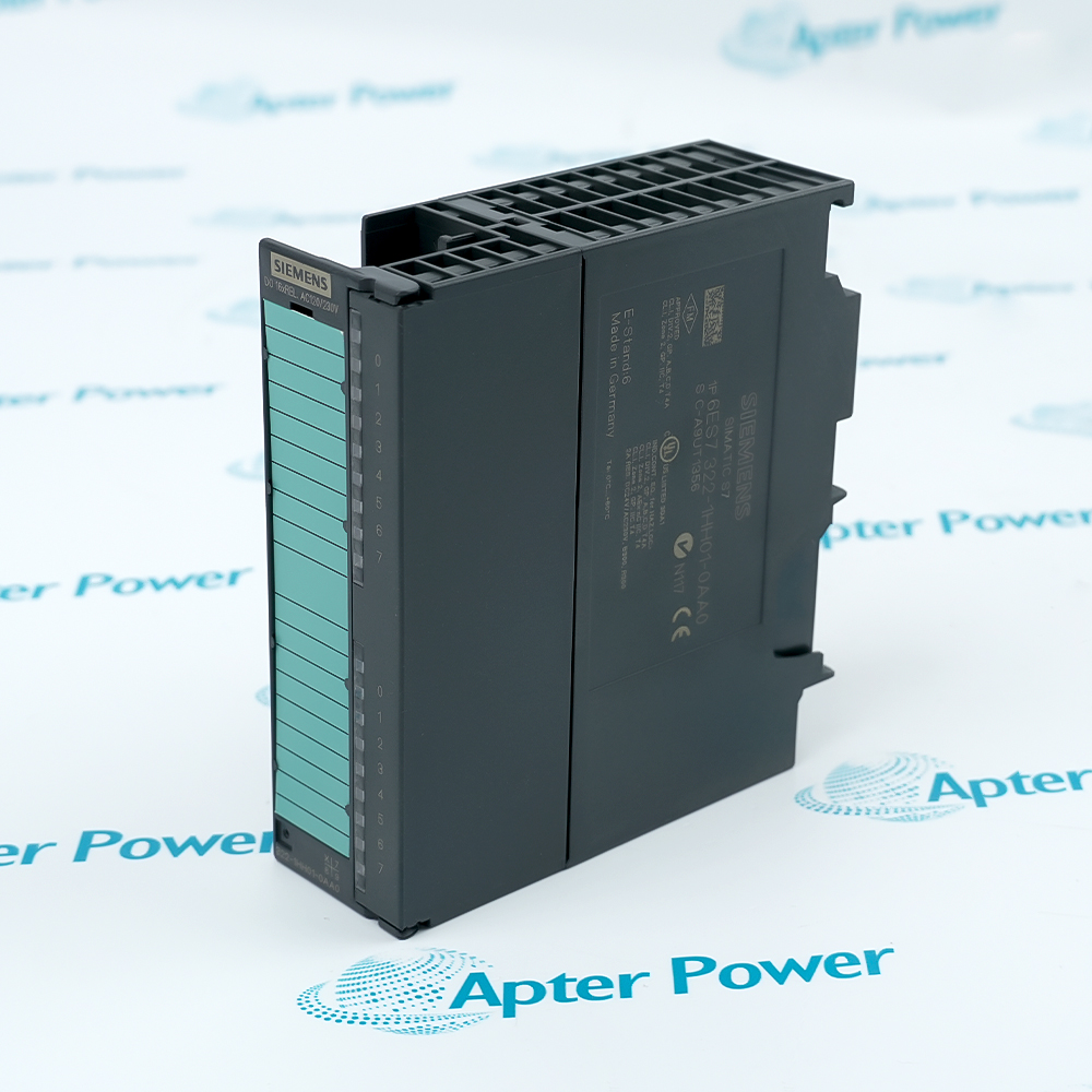
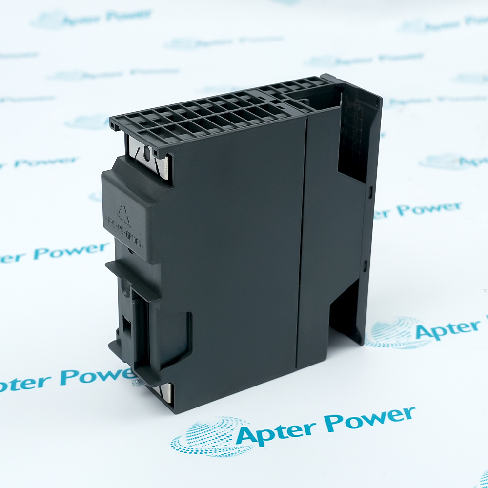
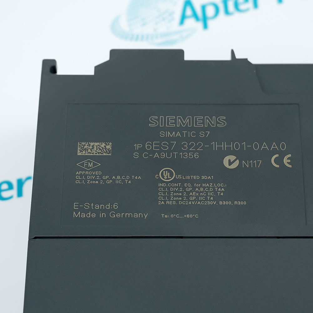
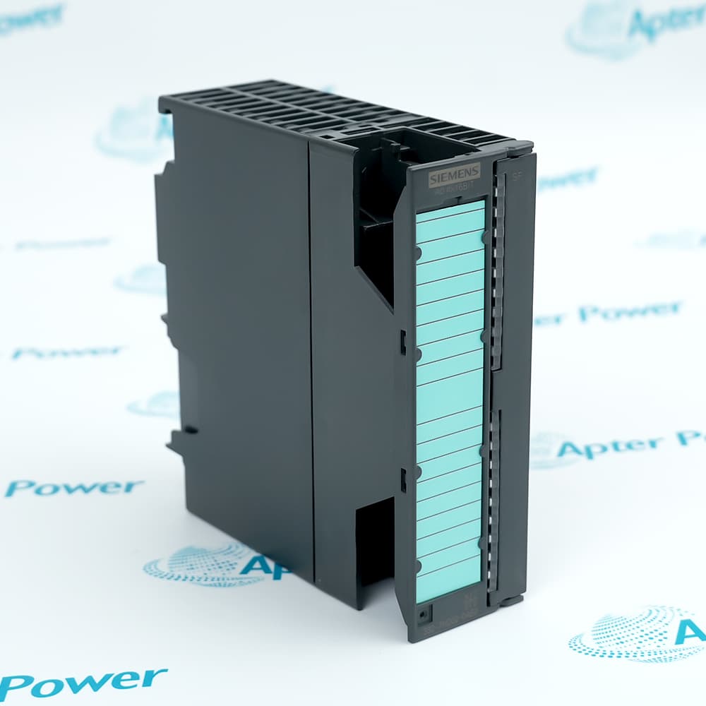
Features:
- Sixteen relay contacts switch supported AC or DC loads from S7-300 output commands.
- Two isolated groups of eight organize the field circuits and their total current.
- Channel LEDs show commanded states, while field protection and fault checking remain external.
Siemens 6ES7322-1HH01-0AA0 transfers controller output bits to mechanical relay contacts.
The two groups inside 6ES7322-1HH01-0AA0 separate field circuits from one another and from the backplane.
Load type and switching duty determine the usable contact behavior of 6ES7322-1HH01-0AA0.
Siemens 6ES7322-1HH01-0AA0 SIMATIC S7-300 SM 322 Relay Output Module Manuals,Datasheets,Link
Important Notice: Other accessories, manuals, cables, calibration data, software, etc. are not included with this equipment unless listed in the above stock item description. All prices are shown in USD.
Output Group Structure
- Channels 0–7: The first eight contacts form one isolated output group.
- Channels 8–15: The second eight contacts form the other isolated output group.
- Group current: Each group must remain within its documented total-current limit.
- Backplane isolation: Optocouplers separate the output groups from the S7-300 backplane electronics.
Contact Duty by Load Type
- Resistive loads: The resistive switching rate follows the documented one-hertz limit.
- Inductive loads: Coils and contactors use the lower switching-frequency boundary.
- Lamp loads: Inrush and power must remain within the stated lamp-load limit.
- Contact life: Voltage, current, load type, and switching frequency together determine operating cycles.
Field Connection Boundaries
- Front connector: The twenty-pin connector carries the relay-group field wiring.
- Coil supply: The relay coils use the documented 24 V DC supply path.
- External protection: Branch fusing and load protection are required because outputs are not short-circuit protected.
- Commissioning: Confirm group commons, field voltage, polarity where relevant, and the load on every channel.
Commanded State and Field Verification
- Channel LEDs: A lit output LED reports the commanded state rather than confirmed field current.
- No wire-break diagnosis: An open field circuit does not create a channel diagnostic from this module.
- No fuse indication: External protective-device status must be inspected separately.
- Fault isolation: Compare the CPU output bit, channel LED, contact continuity, field voltage, and load response in sequence.