Ask our team:
  • Phone: +86 181 0690 9650
  • E-Mail sales1@apterpower.com
  • Lifecycle status

    Active / Available from OEM
    Apter Power provides quotations, sourcing support and host-system documentation for this exact Yokogawa module.

AIP562 S1

/ 4.9
1001 reviews | Need a Specific Revision?
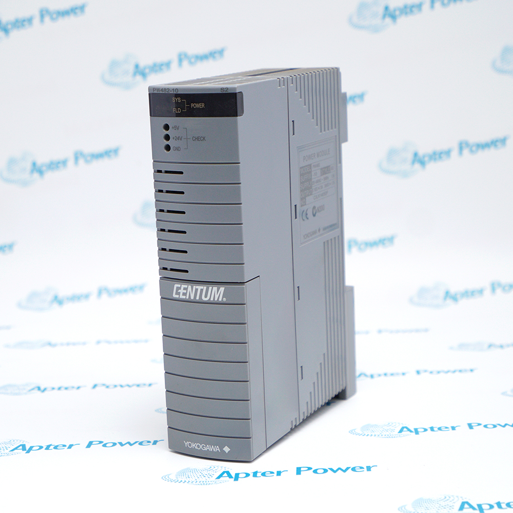
Yokogawa AIP562 S1 is an RL Bus interface module with BUS1 connection and front status indicators for service observation.
In Stock
Ships by Thursday, October 29
Fast Shipping Available
Get a quick price for AIP562 S1
Quantity
*E-mail
Company
*Mobile
*Content
Upload (gif, jpg, jpeg, png, bmp, doc, docx, xls, xlsx, ppt, pdf, csv)

Technical specifications for AIP562 S1

  • Manufacturer:
    Yokogawa
  • Part Number:
    AIP562 S1
  • Product Family:
    Yokogawa DCS system
  • Product Type:
    RL Bus Interface Module
  • Stock:
    1
  • Weight:
    0.44 kg
  • Estimated shipping dimensions:
    5x25x12.7cm
  • Tariff Code:
    Please confirm the destination before shipping
  • Country of origin:
    Japan
  • Place of shipment:
    Xiamen,Fujian,China
By purchasing this item, you agree to the Terms & Conditions, ApterPower is not an authorized distributor for listed manufacturers or tradenames and therefore the manufacturer's warranty does not apply. All our products come with ApterPower's 1-year warranty.

More Information

Overview Manuals Bus Operation Status Review Service Method Applications

Features:

  • RL Bus interface: BUS1 provides the visible connection point for the documented host position.
  • Status landmarks: RCV, SND-L, SND-R and ENBL give technicians observable service references.
  • Style-controlled match: Model AIP562 and Style S1 define the replacement hardware boundary.
The module page connects exact hardware identity with the front observations technicians can use during an outage.

A recorded indicator pattern is most useful when it is tied to the host slot, BUS1 connection and system event history.

Replacement acceptance then follows the approved project procedure rather than a visual assumption about another style.

Apter Power supports Yokogawa AIP562 S1 RL Bus Interface Module sourcing with model/style review and host-record coordination.
Yokogawa AIP562 S1 RL Bus Interface Module Manuals,Datasheets,Link Important Notice: Confirm the complete model, configuration and host-system records before replacement.
  • Interface point: BUS1 is the front connection associated with the RL Bus module identity.
  • Receive landmark: RCV provides an observable status point for the installed service baseline.
  • Send landmarks: SND-L and SND-R provide two separately labelled transmit-side observations.
  • Enable landmark: ENBL adds a visible state reference that should be interpreted through the host procedure.
  • Baseline pattern: Record all four indications before isolation whenever the operating condition permits.
  • Event correlation: Compare indication changes with host alarms and the timing of the maintenance activity.
  • Connection check: Reconcile the BUS1 connection and seating before attributing a symptom to the module.
  • Meaning boundary: Use the approved project procedure for state interpretation rather than the label text alone.
  • Host record: Retain the rack, slot, model and Style S1 identity in one change record.
  • Physical handling: Protect the mating connector and compare orientation before insertion.
  • Staged restoration: Restore the documented connection before evaluating the post-service indicator pattern.
  • Acceptance: Use the site communication and alarm checks to confirm the host position has returned to service.
  • RL Bus service: Supports a documented Yokogawa RL Bus interface position.
  • Status-based maintenance: Provides visible landmarks for pre-service and post-service comparison.
  • Controlled spares: Keeps the exact model/style tied to a known host-rack assignment.
Description
AIP562 S1 is identified as a Yokogawa RL Bus interface module with a BUS1 front connection. Its exact model and Style S1 label establish the hardware boundary for a documented host-rack position.

The RCV, SND-L, SND-R and ENBL indicators on AIP562 S1 give technicians visible operating landmarks. Recording the installed pattern before intervention creates a useful baseline for comparison, while the approved system procedure remains the source for interpreting normal and abnormal states.

A controlled replacement of AIP562 S1 links the module label, host slot, BUS1 connection and pre-service status record. This approach helps maintenance teams distinguish a hardware mismatch from a connection or system-state issue during restoration.
Alternative Names
AIP562S1 AIP562-S1 AIP 562 S1 AIP 562-S1 Yokogawa AIP562 Style S1 AIP562 Style 1 AIP562 SI AIP56Z S1
Technical notes
AIP562 S1 exposes RCV, SND-L, SND-R and ENBL indicators beside its BUS1 interface, but the front labels alone do not define normal timing or fault logic. Capture the installed indication pattern and rack state before service, then interpret any change through the approved Yokogawa project and maintenance procedure.
Exceptional Service

Our Mission

  • 100% Satisfaction

    We believe expertise is priceless. With over 20 years of experience, and top engineers on staff, we can help you solve or avoid problems that threaten your business.
  • Trust Guaranteed

    Not only do we have a vast inventory, our team makes sure every piece of equipment is in working condition. Your purchases are also backed by our Warranty.
  • Expertise

    Time is money, especially when your equipment is down. We work quickly to get your equipment on its way so you can get it back up and running.

FAQS

The following is a list of questions commonly asked by our customers. Please contact us if you have a question about our process that is not answered below.
What operating information should be captured from AIP562 S1 before a planned shutdown?
Record the RCV, SND-L, SND-R and ENBL indication pattern, the BUS1 connection, host rack and slot, plus any concurrent system alarm. This provides a practical baseline for comparing the module after restoration.
How should technicians interpret a changed indicator pattern on AIP562 S1 after replacement?
Treat the change as a diagnostic entry point rather than a complete fault diagnosis. Compare the pre-service baseline, BUS1 connection and host-system events, then follow the approved Yokogawa procedure for that project.
Can an AIP562 with another Style code replace AIP562 S1?
The shared base model does not establish interchangeability. The offered style should be reconciled with the installed rack record and approved project documentation before it is accepted for service.
What should be checked when AIP562 S1 powers up but BUS1 communication is not restored?
Start with the documented connector seating, host-slot assignment and the relationship between RCV/SND indications and the system event record. This separates a connection or host-state issue from an unverified module substitution.
Which details make a repair report for AIP562 S1 useful to the site team?
The report should retain the exact model/style, serial or traceability reference, observed indicator behavior, connector condition and the rack position used for acceptance. These details support a repeatable return-to-service decision.

Product Browsing History