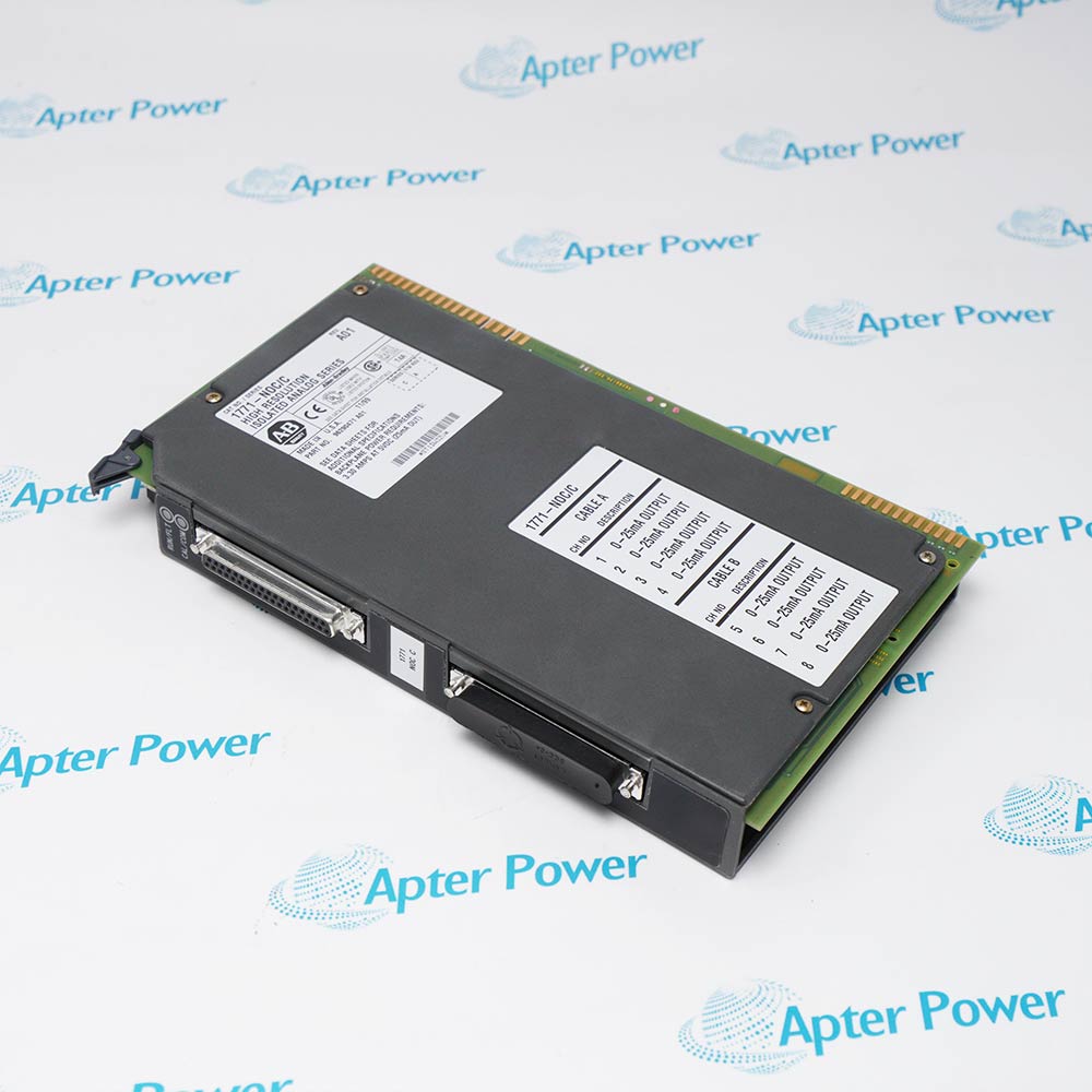
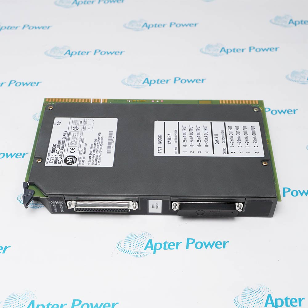
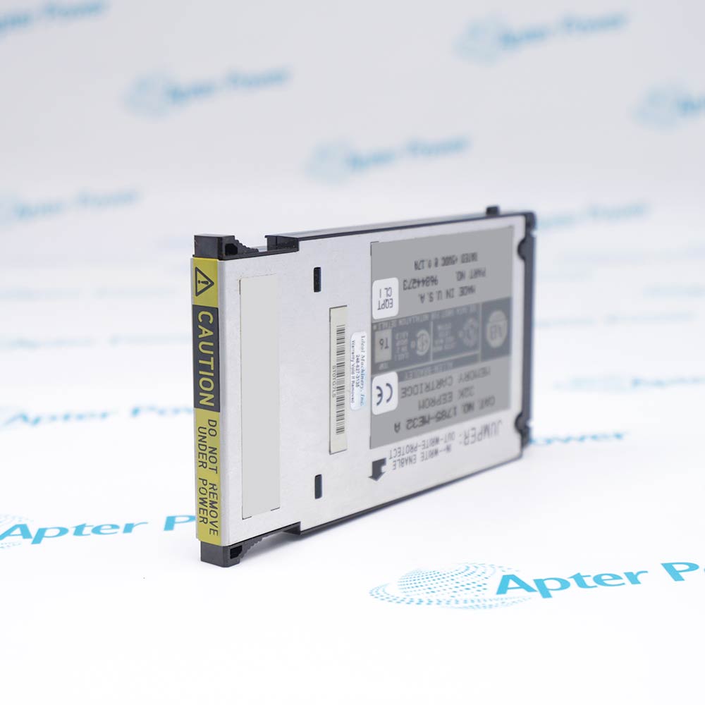
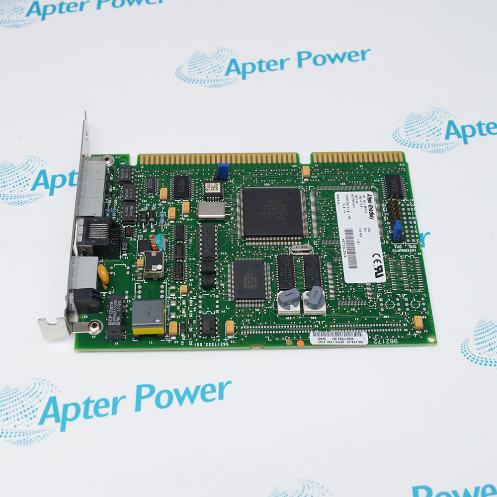
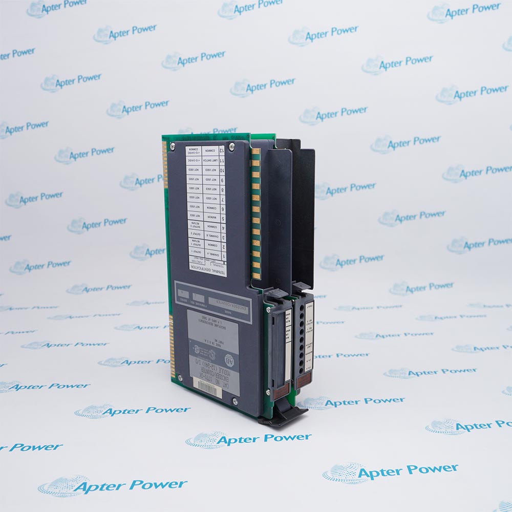
Features:
- Provides High-Resolution Analog Signal Conversion Between Field Devices and the 1771 Rack Backplane
- Incorporates 16-Bit Input and 14-Bit Output Capability with Programmable Reset Support
- Works in Conjunction with PLC-5 and Standard 1771 Series Control Systems
The Allen-Bradley 1771-NOC/C operates as the High-Resolution Isolated Analog I/O Module in a 1771 rack, providing precise current loop outputs and accurate analog signal processing for all control modules within the system. It continuously converts digital setpoints to analog output signals ranging from 0 to 25 mA with 14-bit resolution, while receiving 16-bit input resolution across its isolated channels, delivering 0.01% typical accuracy based on 65,000 count capability over Full-Scale Range (FSR), with offset drift of ±1.0 µA per degree Celsius and gain drift of ±50 ppm per degree Celsius.
The 1771-NOC/C provides essential analog I/O functions common to the entire control rack, and is a critical component of the control path, directly affecting the proper, normal operation of the overall control system. One or more 1771-NOC/C modules are required per rack depending on the desired analog channel count. The module draws a maximum backplane current of 1.1 A with a power dissipation of 5.5 Watts at 5 Volts, and maintains relative humidity tolerance between 5% and 95% without condensation. When handling the 1771-NOC/C during installation or maintenance, operators must strictly follow the guidebook procedures, as this module is sensitive to electrostatic discharge, which can cause internal damage and affect normal operation.
For Safe-State Output applications, the 1771-NOC/C supports programmable reset values configured independently for each output channel. In addition to standard hold-last-state operation, the reset configuration also performs automatic output restoration. The 1771-NOC/C executes channel resets using the internal circuitry specified in the analog output options. Using this method, the module continually monitors the output state of each channel. If the system detects that the primary control signal is no longer providing stable output (outside configured current/tolerance levels), it will automatically transfer the channel to the programmed reset value and place the output in the configured safety state.
The 1771-NOC/C Allen-Bradley N-Series Analog I/O Module may still be available for purchase and support from Apter Power beyond End-Of-Life (EOL) by the manufacturer (OEM).
Allen-Bradley 1771-NOC/C N-Series Analog I/O Module Manuals,Datasheets,Link
Important Notice: Other accessories, manuals, cables, calibration data, software, etc. are not included with this equipment unless listed in the above stock item description. All prices are shown in USD.
Allen-Bradley 1771-NOC/C N-Series Analog I/O Module Specs
General
- Manufacturer Allen-Bradley
- Model 1771-NOC/C
- Condition New Original ready stock
- Product Family 1771-NOC,1771-NOV,1771-NIV
Important Notice: Other accessories, manuals, cables, calibration data, software, etc. are not included with this equipment unless listed in the above stock item description. All prices are shown in USD.
- Proportional Valve Control: Regulates the opening percentages of pneumatic and hydraulic flow valves.
- Motor Speed Regulation: Sends target velocity references to Variable Frequency Drives (VFDs).
- Process Signal Emulation: Simulates analog loop instrumentation during system testing.
- Isolated Loop Controls: Prevents electrical cross-talk in chemical, water, and manufacturing plants.
- Power Down: Turn off all electrical power to the 1771 I/O chassis before insertion.
- Set Jumpers: Configure the onboard hardware jumpers for target "Last State" fault behaviors.
- Insert Module: Slide the module into any available chassis slot except the leftmost processor slot.
- Attach Wiring Arm: Secure the dedicated 1771 Field Wiring Arm onto the module pivot pins.
- Secure Latches: Close the top and bottom chassis latching arms to lock the unit in place.
- Field Wiring: Connect field devices directly to the removable terminal blocks on the wiring arm.
- Data Blocks: Program Block Transfer Write (BTW) instructions to send configuration and output data.
- Status Monitoring: Program Block Transfer Read (BTR) instructions to capture real-time diagnostic flags.
- Thermal Management: Limit the power dissipation of adjacent slots to 10 Watts maximum.