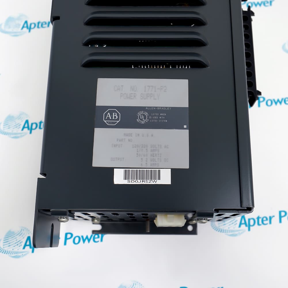
AB 1771-P2
AB 1771-P2
AB 1771-P2
AB 1771-P2
AB 1771-P2
AB 1771-P2
Ask our team:
  • Phone: +86 181 0690 9650
  • E-Mail sales1@apterpower.com
  • Lifecycle status

    Discontinued
    Discontinued date: 2017-12-31
    Replacement category: Engineering Replacement

1771-P2

/ 4.9
1001 reviews | Need a Specific Revision?
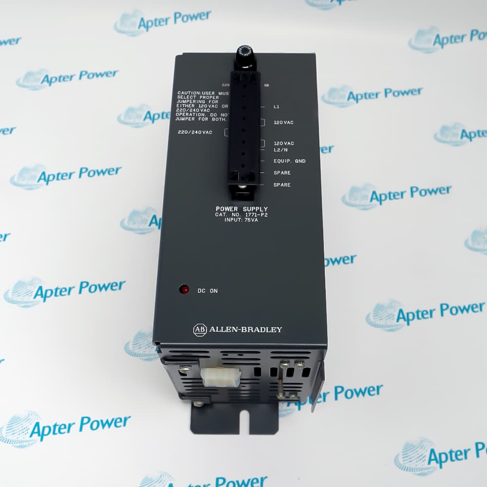
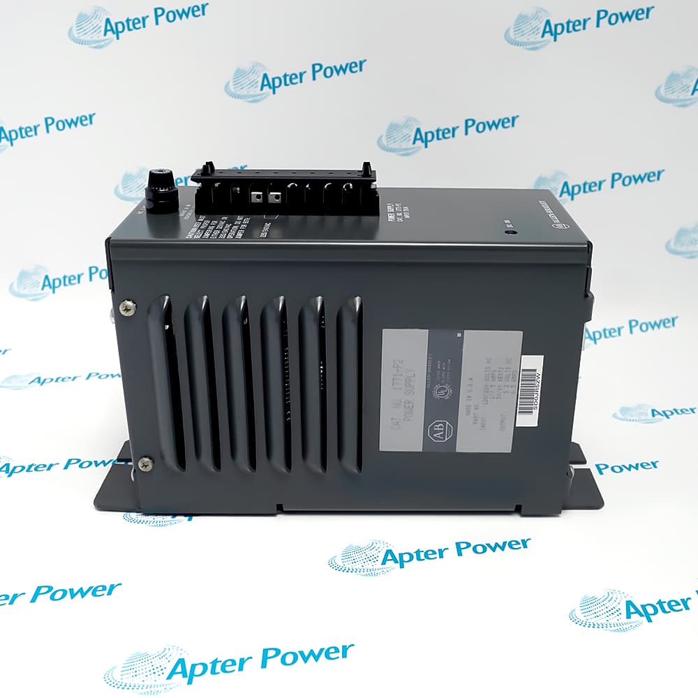
Allen-Bradley 1771-P2 is an auxiliary supply delivering regulated 5.1 V DC backplane power to one compatible 1771 I/O chassis.
In Stock
Ships by Wednesday, October 28
Fast Shipping Available
Get a quick price for 1771-P2
Quantity
*E-mail
Company
*Mobile
*Content
Upload (gif, jpg, jpeg, png, bmp, doc, docx, xls, xlsx, ppt, pdf, csv)

Technical specifications for 1771-P2

  • Manufacturer:
    Allen-Bradley
  • Part Number:
    1771-P2
  • Product Family:
    PLC-5
  • Product Type:
    Auxiliary Power Supply
  • Stock:
    1
  • Input Voltage:
    120 V AC or 220/240 V AC, selectable
  • Input Voltage Range:
    98…132 V AC or 196…250 V AC
  • Input Frequency:
    50/60 Hz
  • Maximum Input Power:
    65 W
  • Maximum Input Apparent Power:
    90 VA
  • Output Voltage:
    5.1 V DC ±5%
  • Maximum Output Current:
    6.5 A
  • Power-loss Delay:
    13.5 ms ±2.5 ms
  • Chassis Capacity:
    One 1771 I/O chassis
  • Chassis Cable:
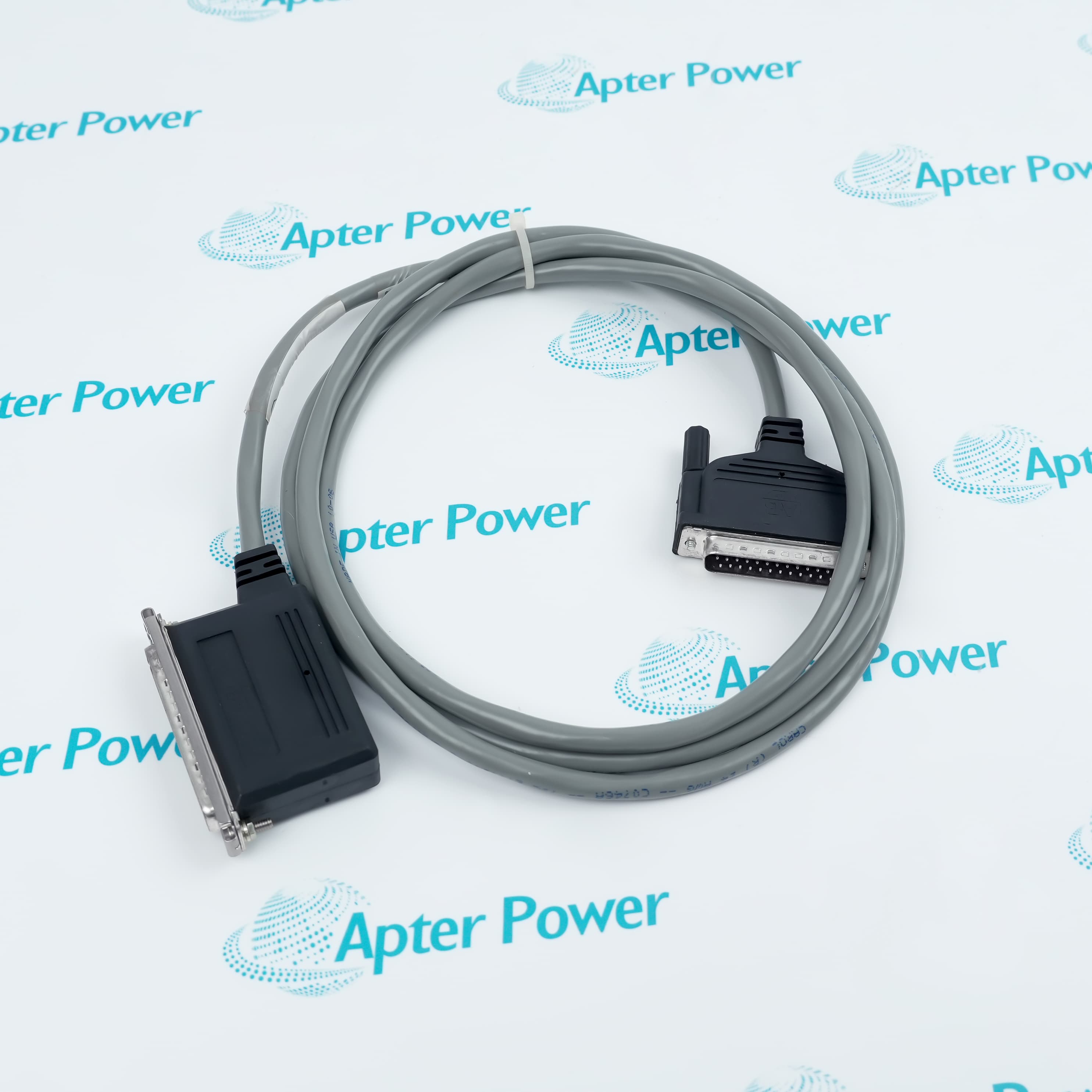
    1771-CE for side mounting; 1771-CD for separate mounting
  • Separate-mount Distance:
    Up to 1.52 m cable distance from the chassis
  • Operating Temperature:
    0…60 °C
  • Storage Temperature:
    -40…85 °C
  • Relative Humidity:
    5…95%, noncondensing
  • Dimensions:
    28.6 × 11.6 × 18.2 cm
  • Weight:
    5.89 kg
  • Tariff Code:
    8504401400
  • Country of origin:
    USA
  • Place of shipment:
    Xiamen, Fujian, China
By purchasing this item, you agree to the Terms & Conditions, ApterPower is not an authorized distributor for listed manufacturers or tradenames and therefore the manufacturer's warranty does not apply. All our products come with ApterPower's 1-year warranty.

More Information

Overview Manuals Input Setup Mounting Diagnostics Application
  • Regulated 5.1 V DC output for one compatible 1771 I/O chassis
  • Selectable 120 or 220/240 V AC input configuration
  • Side-mounted or separately mounted chassis connection using the specified cable

1771-P2 is an Allen-Bradley auxiliary power supply designed for documented PLC-5/1771 and Mini-PLC-2 power arrangements.

It delivers up to 6.5 A of regulated backplane current and provides a D.C. ON indicator for basic operating-state diagnosis.

Before installation or replacement, verify input voltage, jumper positions, fuse, output load, mounting location, chassis cable, grounding, and cooling clearance.

Availability, condition, price, and shipping time for 1771-P2 are confirmed during quotation.

Allen-Bradley 1771-P2 Auxiliary Power Supply Manuals, Datasheets, Links

Important Notice: Other accessories, manuals, cables, calibration data, software, etc. are not included with this equipment unless listed in the above stock item description. All prices are shown in USD.
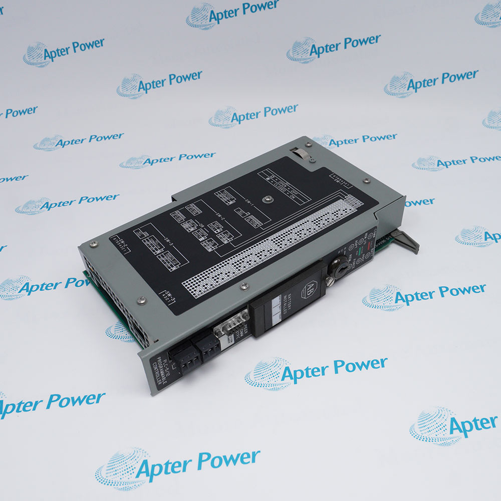

  • Factory shipping configuration is 120 V AC
  • Metal jumpers select the documented 120 or 220/240 V AC arrangement
  • Fuse rating must match the selected input-voltage configuration
  • 1771-CE supports mounting immediately to the left of the I/O chassis
  • 1771-CD supports approved panel mounting within 1.52 m cable distance
  • Separate mounting is permitted above or beside the chassis, never below it
  • D.C. ON indicates that regulated output power is present
  • An unlit indicator can result from low or high input voltage
  • Fuse failure or output overcurrent can also remove the regulated output
  • Auxiliary backplane power for one 1771 I/O chassis containing an adapter module
  • Power supply service for documented Mini-PLC-2 controller installations
  • Power supply service for documented Mini-PLC-2/15 controller installations
Description
1771-P2 is an Allen-Bradley auxiliary power supply for one compatible 1771 I/O chassis or documented Mini-PLC-2 installation.

The unit accepts selectable 120 or 220/240 V AC input and supplies regulated 5.1 V DC backplane power through a 1771-CE or 1771-CD cable.

Before installation or replacement, confirm input jumpers, fuse rating, chassis load, cable type, mounting position, ventilation, and the absence of any battery-backup requirement.
Alternative Names
1771-P2 1771 P2 1771P2 Allen-Bradley 1771-P2 Allen Bradley 1771-P2 AB 1771-P2 Rockwell Automation 1771-P2
Technical notes
Allen-Bradley 1771-P2 supplies one 1771 chassis through 1771-CE or 1771-CD. Verify input jumpers, fuse, backplane load, mounting position, ventilation, and battery-backup needs before energizing.
Exceptional Service

Our Mission

  • 100% Satisfaction

    We believe expertise is priceless. With over 20 years of experience, and top engineers on staff, we can help you solve or avoid problems that threaten your business.
  • Trust Guaranteed

    Not only do we have a vast inventory, our team makes sure every piece of equipment is in working condition. Your purchases are also backed by our Warranty.
  • Expertise

    Time is money, especially when your equipment is down. We work quickly to get your equipment on its way so you can get it back up and running.

FAQS

The following is a list of questions commonly asked by our customers. Please contact us if you have a question about our process that is not answered below.
Can Allen-Bradley 1771-P2 power more than one 1771 chassis?
No. Rockwell specifies one I/O chassis. Calculate that chassis's complete backplane load and keep it within the supply's output rating before installation.
Does Allen-Bradley 1771-P2 provide battery backup for processor memory?
No. Rockwell directs applications requiring battery backup to the 1771-P1 arrangement. Do not infer memory retention from the 1771-P2 backplane supply.
Which cable should be used when Allen-Bradley 1771-P2 is mounted beside the chassis?
Use the 0.30 m 1771-CE cable for left-side chassis mounting. The 1.52 m 1771-CD cable serves an approved separately mounted supply.
Why must Allen-Bradley 1771-P2 not be mounted below the I/O chassis?
Rockwell prohibits that position because convection cooling must serve both units. A separately mounted supply goes above or beside the chassis with specified vertical clearance.
What must change before Allen-Bradley 1771-P2 is connected to 220/240 V AC?
Reposition the input-voltage jumpers and install the documented fuse for the selected input. The supply is factory-shipped for 120 V AC operation.
What does an unlit D.C. ON indicator mean on Allen-Bradley 1771-P2?
Rockwell identifies three principal causes: input voltage outside range, a blown fuse, or output overcurrent. Isolate and test those conditions before replacing the supply.
How should an isolation transformer be sized for Allen-Bradley 1771-P2?
Use the manufacturer's transformer recommendation when available; otherwise Rockwell's installation data applies a 2.5 multiplier to the real-power value taken from the load graph.