Fast Quote
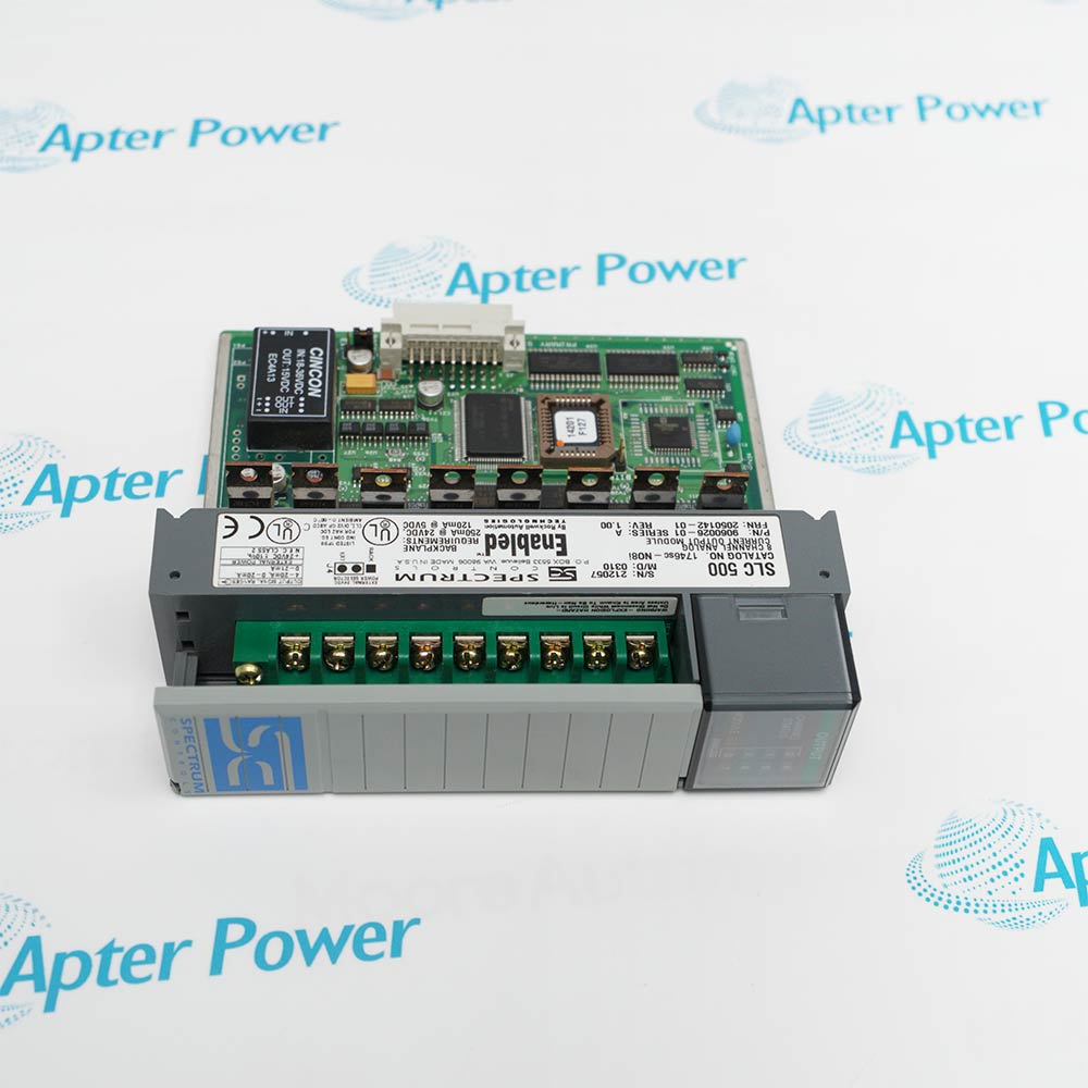
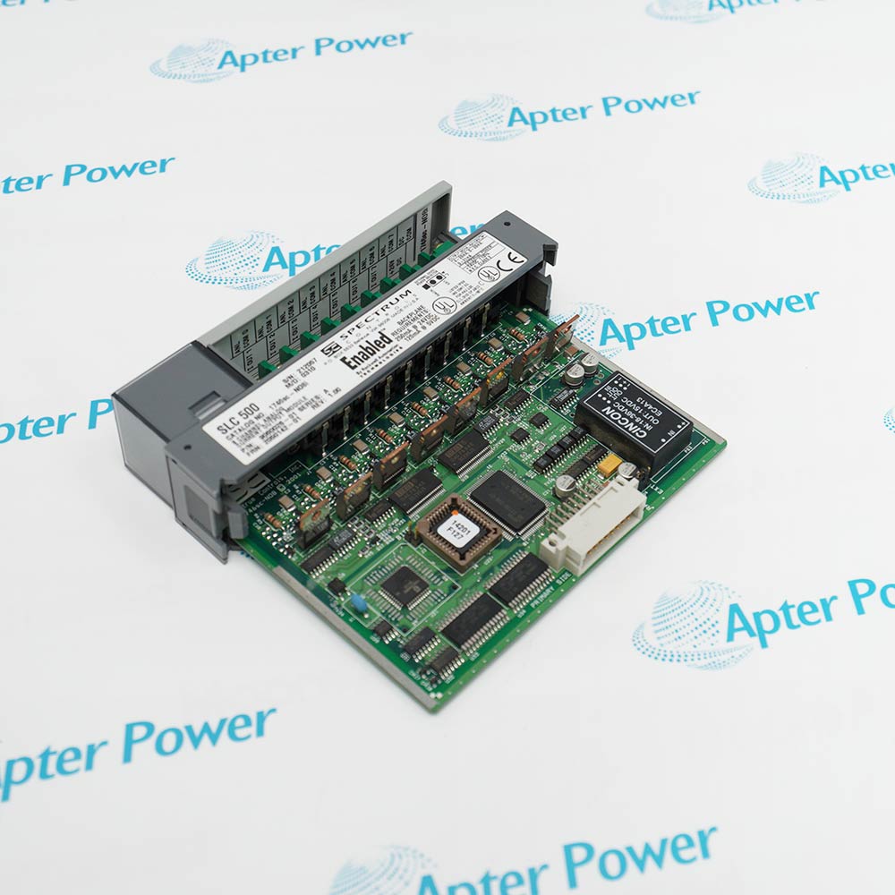
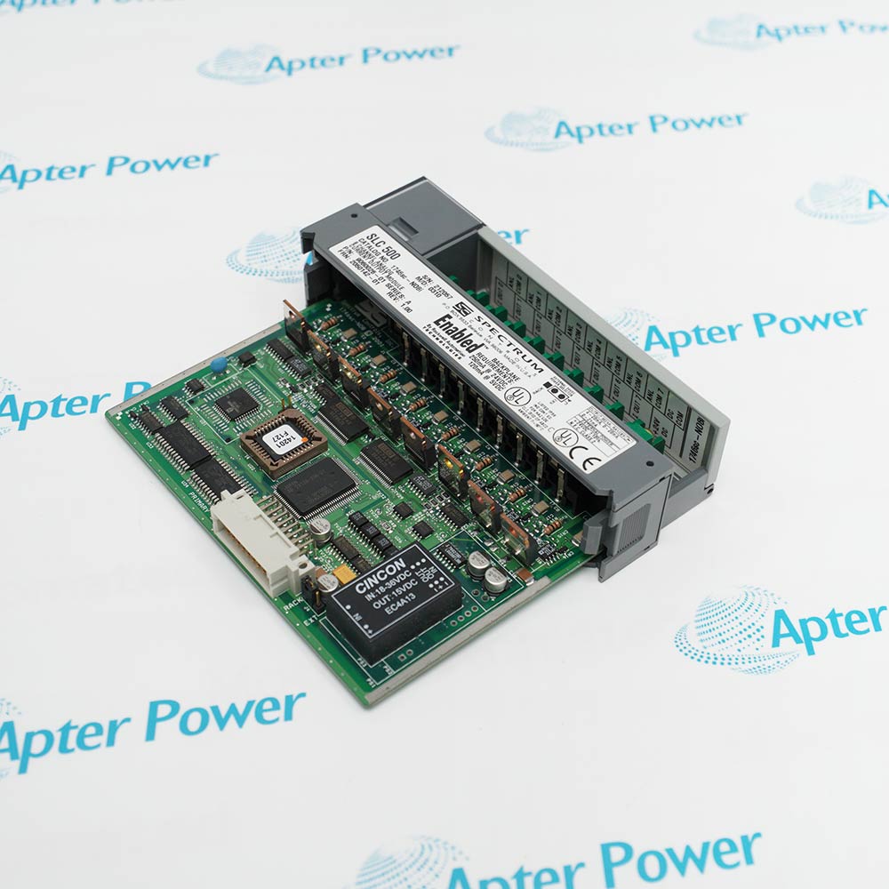

1746SC-NO8I commissioning centers on matching each field loop to its configured output range and operating class before the module is placed in service.
Choose the backplane or external 24 V DC supply arrangement first, then retain the documented Class 1 or Class 3 image size and module ID in the SLC 500 project.
For replacement, compare the saved scaling, clamp, ramp, alarm, and fault-value settings with the connected load, J4 position, and field wiring.
Spectrum Controls 1746SC-NO8I Manuals, Product Family, Links
 Spectrum Controls 1746SC-NO8I DatasheetBrowse Allen-Bradley SLC 500 Product ListingsReview Apter Power Service and Support Information
Important Notice: Other accessories, manuals, cables, calibration data, software, etc. are not included with this equipment unless listed in the above stock item description. All prices are shown in USD.


APTER.COM is an official website owned and operated by Apter Power Limited.All rights reserved.
Apter Power is not an authorized distributor or representative of the manufacturers featured on this website.All brand names and trademarks are the property of their respective owners.