Key Distinctions Between DCS Cards and PLC Modules for Industrial Control
About the author
Written by May, Managing Director of Apter Power
May's Facebook:
May has been working at Apter Power for 10 years, where she turns complex power-automation challenges into clear, executable plans.
Drawing on deep product knowledge and field-proven methodologies, she has already supported 2 000+ customers in over 100 countries, maintaining a 96 % satisfaction score.
Industrial plants rarely struggle because they picked the “wrong” controller. Trouble shows up when control, monitoring, and protection responsibilities spread across platforms, and the boundary has no owner. During upgrades and spare-part sourcing, often through suppliers such as Apter, revision control and interchangeability can decide what is practical on the floor. The sections below separate the roles of DCS cards and PLC modules, then place machinery monitoring and protection hardware where it belongs.
Why Industrial Facilities Use Both Control Systems and Machinery Monitoring
Operations need stable production. Reliability needs early warning and decisive protection. Those goals overlap, but they drive different design choices, so plants commonly deploy both a control system and a dedicated monitoring layer.
Failure mode mismatch: process deviations are corrected by control action; rotating equipment faults need condition trending and protection logic.
Integrity expectations: many turbomachinery programs align protection functions with standards such as API 670.
Stakeholder needs: operators need actionable alarms; maintenance needs diagnostic context and history.
With that split agreed, the architecture stays clean: DCS cards and PLC modules run the process, while monitoring systems focus on asset health and protection.
Control Layer Architecture: DCS I/O Cards vs PLC Modules
Control-layer architecture affects commissioning effort, fault containment, and the way changes are governed over time. The comparison below focuses on where PLC-based designs excel in discrete control, and where DCS architecture earns its keep in continuous operations.
PLC System Structure for Discrete Control
A PLC-based architecture usually maps to a machine, skid, or discrete area. It fits well when sequencing, permissives, and interlocks dominate and when the equipment package has clear ownership.
In that environment, PLC modules are selected using constraints that are concrete and testable:
Point type and wiring conventions
Required scan behavior and response time for discrete logic
Environmental ratings and cabinet layout
Network compatibility for remote I/O and integration
FAT and SAT workflow for packaged equipment
PLC projects also benefit from containment. A packaging line can change without forcing a plant-wide engineering database update.
DCS Architecture for Continuous Operations
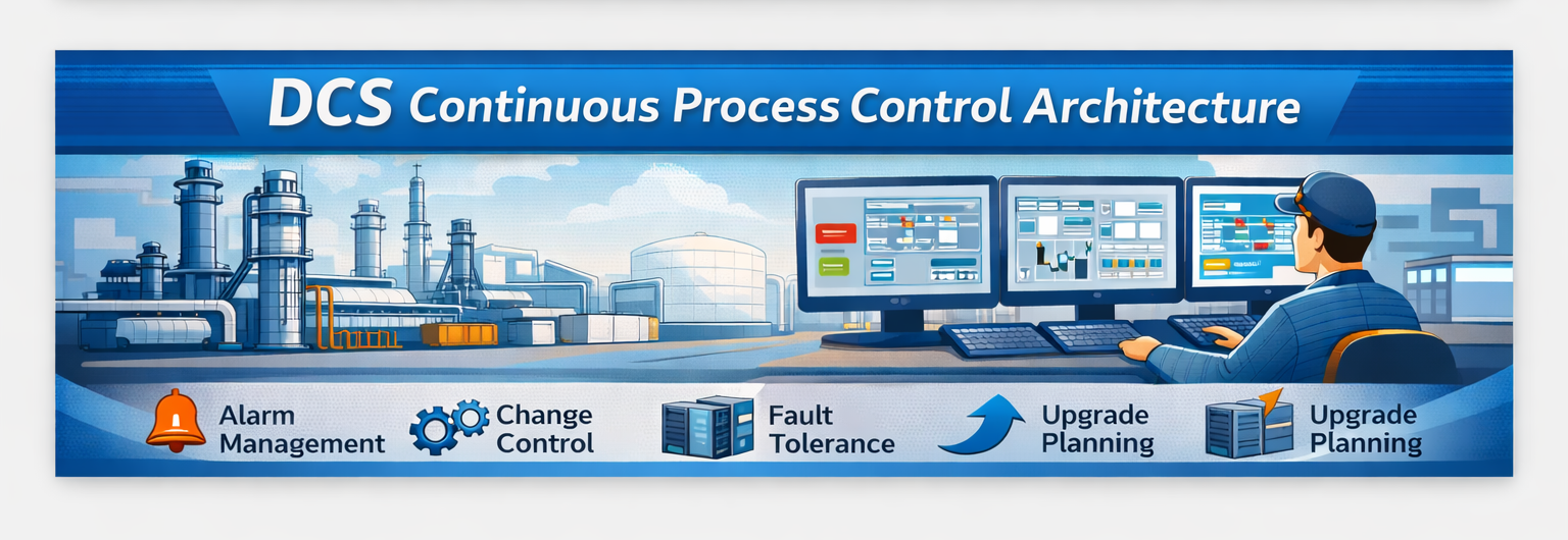
A DCS architecture is usually built around consistent engineering standards, operator experience, and lifecycle governance across many units. The key advantage is coherence through years of changes: alarms stay consistent, naming conventions remain stable, and engineering practices hold together across multiple teams.
In DCS-centric environments, DCS I/O cards are evaluated as part of a broader platform decision:
Alarm management standards across units
Change control and configuration governance
Redundancy and fault handling patterns
Upgrade path planning
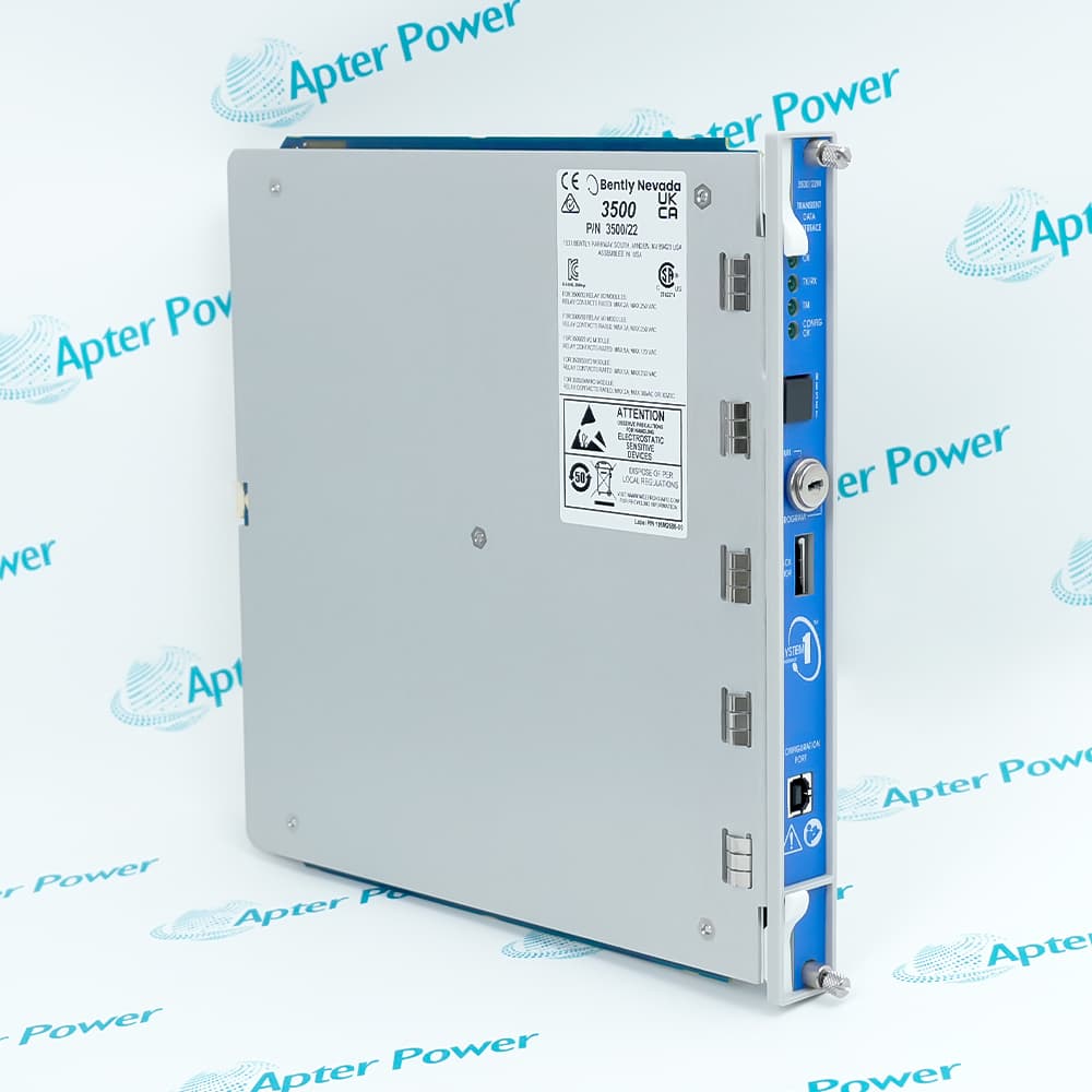
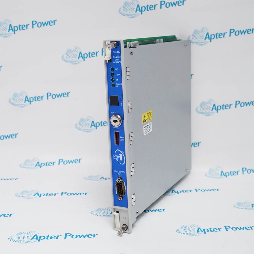
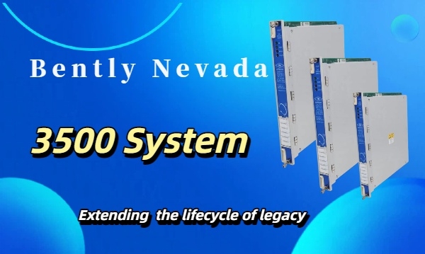
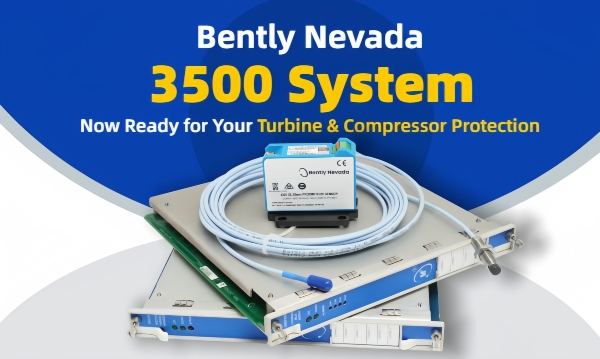
Many sites also run a dedicated machinery monitoring rack alongside the DCS. A Bently Nevada 3500 rack often appears as a separate machinery layer that delivers alarm and protection signals to the control layer. Specifications may reference 3500/22 and the more current 3500/22M, along with output modules such as 3500/33 for discrete alarm or trip contacts.
Key Functional Differences Between PLC Modules and DCS Cards
PLC modules and DCS cards both support control I/O, yet they tend to optimize different things. PLC-oriented designs often prioritize local autonomy and discrete sequencing. DCS-oriented designs often prioritize unit-wide consistency and long-lived governance. The distinction becomes clearer once machinery monitoring enters the discussion.
Control Logic Execution vs Continuous Data Acquisition
Control I/O exists to execute logic and drive outputs. Monitoring exists to continuously acquire dynamic behavior and interpret conditions. That distinction sits behind the long-tail query difference between DCS and PLC modules: the control layer can be implemented in more than one way, but the monitoring layer solves a different problem.
Teams sometimes frame the comparison as “DCS monitoring cards vs PLC I/O modules.” Generic I/O can pass a value to a historian. It rarely delivers machinery-focused context such as stable event capture, buffered dynamics, or protection-oriented alarming.
This also influences selection work. When people ask how to choose DCS cards for industrial automation, the practical answer usually starts with the operating model. Sites that expect unified alarm governance, consistent graphics, and disciplined change control often lean toward DCS cards for process control. Sites that expect rapid local change around skids and discrete areas often lean toward PLC modules there.
Signal Processing and System-Level Reliability
Machinery monitoring and protection modules are built around the signal chain and the integrity of outputs. In the 3500 family, spares lists often include modules such as:
3500/32 relay output modules used to deliver alarm or trip contacts to the control
3500/42 monitoring modules used in proximity and seismic measurement contexts
3500/50M tachometer monitoring modules used for speed-related measurements
Those functions are not simple “I/O equivalents.” They represent purpose-built behavior around signal conditioning, alarming, and protection output discipline.
Alarm and trip contacts, curated health indicators
When a DCS-Based Approach Makes More Sense Than PLC Modules
Some plants standardize heavily on PLCs and still succeed. Others standardize on DCS and succeed. The deciding factor is the operating model, the coupling between loops, and how much governance the site can maintain over time. This section focuses on two situations where DCS-centered choices often reduce long-term friction.
Turbomachinery and Rotating Equipment Use Cases
Rotating equipment introduces mechanical risks that do not map cleanly to generic control I/O. A machinery protection layer tracks machine behavior and enforces limits.
Many plants allocate these responsibilities to a dedicated platform, such as Bently Nevada 3500, and integrate it into the control layer. Specifications frequently reference:
3500/22M in the rack interface and data access context
3500/25 in phase reference workflows around Keyphasor signals
If older documents list 3500/22, treat it as a cue to confirm the exact ordering basis and revision used in the site standard before procurement.
Continuous Units With High Availability Needs
High-availability plants are designed around predictable behavior during disturbances and maintenance windows. A DCS operating model often matches that expectation because it supports consistent governance across units and stable operating standards.
In machinery monitoring, similar expectations show up around alarm integrity and repeatable condition history. In many implementations, 3500/42M appears in proximity and seismic contexts where teams want consistent alarming behavior aligned with reliability workflows.
Centralized Monitoring and Asset Protection Considerations
Once a monitoring layer exists, the next decision is how to organize it. Decentralized monitoring can work for a small number of assets, but it often fragments ownership and slows incident response. Centralized monitoring builds a shared record and a shared operating language.
Central monitoring turns scattered readings into a shared history across trains and shifts. That improves:
Event triage speed, because the evidence is already organized
Cross-team alignment, because alarms and trends are interpreted consistently
Outage planning, because risk discussions rely on history rather than anecdotes
Sensors and Interfaces in Protection Chains
A protection system is only as good as the signal chain. False alarms often trace back to sensor selection, installation practice, or mismatched ordering options.
For 3300 XL proximity probe chains, spares lists commonly include identifiers such as 330130-040-01-00 and 330180-90-00. Use them as procurement references, then confirm the configuration against project requirements for system length, mounting style, approvals, and environmental constraints. This is also the right place to align on sensor-chain spares philosophy, since sensor issues can burn outage labor and mimic machinery faults.
Integration Methods: Connecting Monitoring Systems to DCS and PLC
Integration works best when it respects ownership boundaries while still giving operations the information needed for safe decisions. The design choice belongs in architecture, before cabinets are built, and I/O is frozen.
Common Integration Paths
1. Discrete alarm and trip contacts into control
Monitoring hardware drives alarm and trip contacts through relay modules, and the control layer consumes those contacts. In 3500 ecosystems, 3500/33 and 3500/32 are commonly referenced for discrete outputs. This approach keeps protection behavior explicit and auditable.
2. Curated condition indicators into DCS or PLC for operator context
Operators benefit from the health context during upsets. Keep signals curated so the control layer receives stable indicators rather than raw diagnostics. This reduces nuisance alarms and avoids “alarm inflation” on the operator console.
3. Transmitter-style signals for basic trending where appropriate
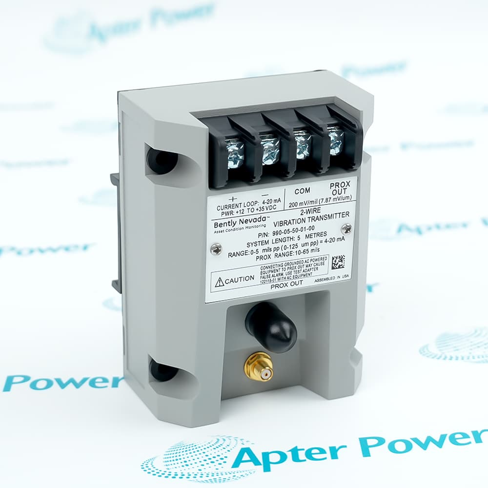
For smaller systems or lower criticality assets, a 4–20 mA vibration signal can support trending in the control layer. In Bently Nevada ecosystems, the 990 vibration transmitter is often used in this style, and ordering codes such as 990-05-50-01-00 and 990-05-70-01-00 may appear in BOMs.
Integration Controls That Prevent Late Rework
Alarm ownership and setpoint approval
Trip governance, bypass rules, and proof testing approach
Event correlation and tag naming across systems
These three items tend to decide whether integration remains stable after commissioning.
Product Selection and Spare Parts Strategy for Long-Term Reliability
Selection decisions show up later as downtime, troubleshooting effort, and the size of the spares cabinet. A practical strategy avoids collecting “one of everything” and instead builds spares around consequence and lead time.
Lifecycle Management and Spare Parts Planning
A workable spares plan splits inventory into buckets that do not overlap:
Protection-critical spares: modules whose absence blocks startup or forces derates. Depending on the architecture, this often includes pieces such as 3500/22M, 3500/33, or 3500/32.
Common monitoring spares: high-usage monitor types aligned to fleet standardization, such as 3500/42, 3500/42M, or 3500/50M.
Sensor-chain spares: probe, extension, and interface elements, where identifiers such as 330130-040-01-00 and 330180-90-00 are frequently standardized.
When sourcing through a broad-line marketplace such as Apter, align early on naming conventions, revision control, and site acceptance rules so procurement, maintenance, and engineering validate the same target identity.
Standalone Monitoring Solutions for Smaller Systems
Smaller assets still benefit from disciplined boundaries. Two common patterns appear in retrofit scopes:
Standalone equipment monitoring using 1900/65A
Transmitter-based trending using 990-series transmitters when full diagnostics are not required, with ordering codes such as 990-05-50-01-00 and 990-05-70-01-00
The deciding factor is the level of protection, integrity, and diagnostic detail the asset requires.
Automation Choices That Grow with Your System
Standards evolve, equipment is replaced in phases, and ownership shifts between contractors and in-house teams. An architecture that scales keeps integration stable while each layer modernizes on its own schedule.
A few practices keep expansion predictable:
Keep protection outputs explicit and auditable.
Keep monitoring tag naming consistent across trains.
Keep control logic modular at unit and package boundaries.
Keep spares strategy aligned to fleet standardization.
Those choices reduce the cost of expansions and help prevent protection redesign during control upgrades.
FAQs About Control Systems and Monitoring Cards
Q1: When Should DCS Cards Be Preferred Over PLC Modules in Industrial Applications?
DCS cards fit continuous units with dense loop interaction, heavy operator workflow, and strict alarm and configuration governance. They support consistent standards across units and upgrades. PLC modules fit packaged skids and discrete sequences where equipment ownership stays local, and changes remain contained.
Q2: Can PLC Modules Handle Vibration Monitoring and Equipment Protection Tasks?
PLC modules can trend vibration via 4–20 mA and support basic visibility. Protection requires dedicated monitoring that interprets the signal chain continuously and drives defined alarm or trip outputs. Transmitter-style signals limit diagnostic depth compared with monitoring systems used on critical rotating equipment.
Q3: How Does Product Selection Impact Long-Term Maintenance and System Scalability?
Selection shapes spares burden, outage readiness, and upgrade flexibility. Standardizing monitor families reduces unique inventory. Clear ownership of alarm setpoints prevents drift. Stable interfaces ,such as relay boundaries and curated summary data, allow DCS or PLC upgrades without redesigning machinery protection. Ordering structures and approvals should be verified during procurement.
Set Clear Boundaries Between Control and Protection
DCS cards and PLC modules control the process. Monitoring and protection modules interpret mechanical behavior and enforce machinery limits. Plants that document the boundary, integrate through well-governed signals, and plan spares around real risk avoid many late-stage surprises. The same discipline keeps upgrades, turnarounds, and obsolescence-driven replacements predictable.
The Strategic Logic Behind Dual-Layer Industrial Control Architectures
Modern industrial facilities operate through two distinct yet complementary layers: one focused on process control and the other on equipment protection. This separation stems from fundamentally different risk profiles—process deviations require continuous correction, while machinery degradation demands trend analysis and definitive protective actions.
The choice between DCS and PLC platforms reflects an organization’s operational philosophy rather than purely technical considerations. DCS environments prioritize governance consistency, standardized alarm management, and long-term maintainability across large continuous processes. PLC-based approaches emphasize modular autonomy, rapid localized changes, and clear equipment-level ownership—making them naturally suited for packaged skids and discrete manufacturing cells.
Machinery monitoring introduces a third architectural layer that transcends the DCS versus PLC debate. Purpose-built monitoring systems handle specialized tasks such as dynamic signal analysis, protection logic execution, and diagnostic data curation—functions that generic control I/O was never designed to perform.






Leave Your Comment