How to Replace a Triconex 3008 Processor Without Process Shutdown: Apter Power Practical Guide
About the author
Written by Leonia, Marketing Director of Apter Power
Leonia's LinkedIn:
Leonia brings 10+ years of automation sales experience, spanning PLC, DCS system integration across Asia, Europe, American. Having delivered 500+ lines for oil & gas clients, she knows where control architectures stall and how to pre-empt costly downtime.
A failed processor in a running safety system creates an urgent but manageable maintenance problem. The process may still be stable, the operator may see only one chassis alarm, and the maintenance team may have one clear FAULT LED on the rack. For plants running a legacy Triconex system, the key question is direct: can the faulty 3008 Main Processor be replaced without shutting down the unit?
In many healthy TMR configurations, online replacement is possible when two processor channels remain healthy, the fault is properly confirmed, and a compatible spare is ready. The real challenge is making the right field decision before anyone touches the rack.
Notes: Technical details should always be verified against the installed system version, site-approved procedures, and the applicable controller documentation before field work.
The True Cost of Hardware Failures in Legacy Systems
The price of a failed 3008 processor is rarely the largest cost. The higher cost comes from production risk, engineering time, delayed maintenance, emergency sourcing, and reduced confidence in a safety layer that is still running with less redundancy than intended.
In a refinery hydrotreater, one failed processor channel may leave the unit online. Operations may continue at the normal rate because two healthy channels remain in control. Even so, the shift supervisor now has a live reliability concern. A second processor fault, an I/O bus issue, or a redundant power supply alarm can quickly change the maintenance decision.
Reduced redundancy until the failed channel is restored
Management attention
Extra approval due to process safety relevance
A chemical plant running an older safety rack gives a typical example. The unit had one MP fault during a stable production campaign. Production did not stop, but the spare on site was untested and the revision label was partly unreadable. Maintenance waited for a confirmed replacement, operations froze all nonessential changes, and engineering reviewed the alarm history every shift. The process never tripped, yet the plant carried avoidable risk for several days.
Zero Disturbance During Active Hardware Faults
The reason online replacement can be considered is the Triple Modular Redundant architecture. Three Main Processors run in parallel, communicate through the TriBus, and vote critical data so a single failed channel can be isolated while the remaining channels continue control.
The strongest Triconex TMR architecture safety benefits appear during a single-channel failure. Each channel executes the control program independently, while voting logic detects and compensates for bad data. A single-channel fault is designed to be isolated so the remaining healthy channels can continue control when the system is operating within its fault-tolerant design conditions.
A healthy operating state before replacement normally looks like this:
Checkpoint
Go Condition
Stop Condition
Processor health
Two MPs PASS, one MP fault isolated
Another MP shows intermittent or active fault
Process status
Stable rate, no active upset, no trip reset activity
A common field error is treating every FAULT LED as a simple module swap. If the fault appears after a cabinet power disturbance, water ingress, vibration event, or recent wiring work, the processor may be the symptom. Good teams pause long enough to verify the wider cabinet condition.
Safe Replacement of the Triconex 3008 Processor Online
The online replacement of Triconex 3008 hardware should be planned as a controlled maintenance task under approved site procedures. Only qualified SIS, instrumentation, or control-system personnel should perform the work.
For legacy plants, the field scope includes fault confirmation, redundancy verification, spare validation, bypass discipline, engineering station access, and post-replacement proof that the controller has returned to full TMR operation.
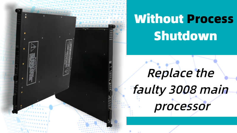
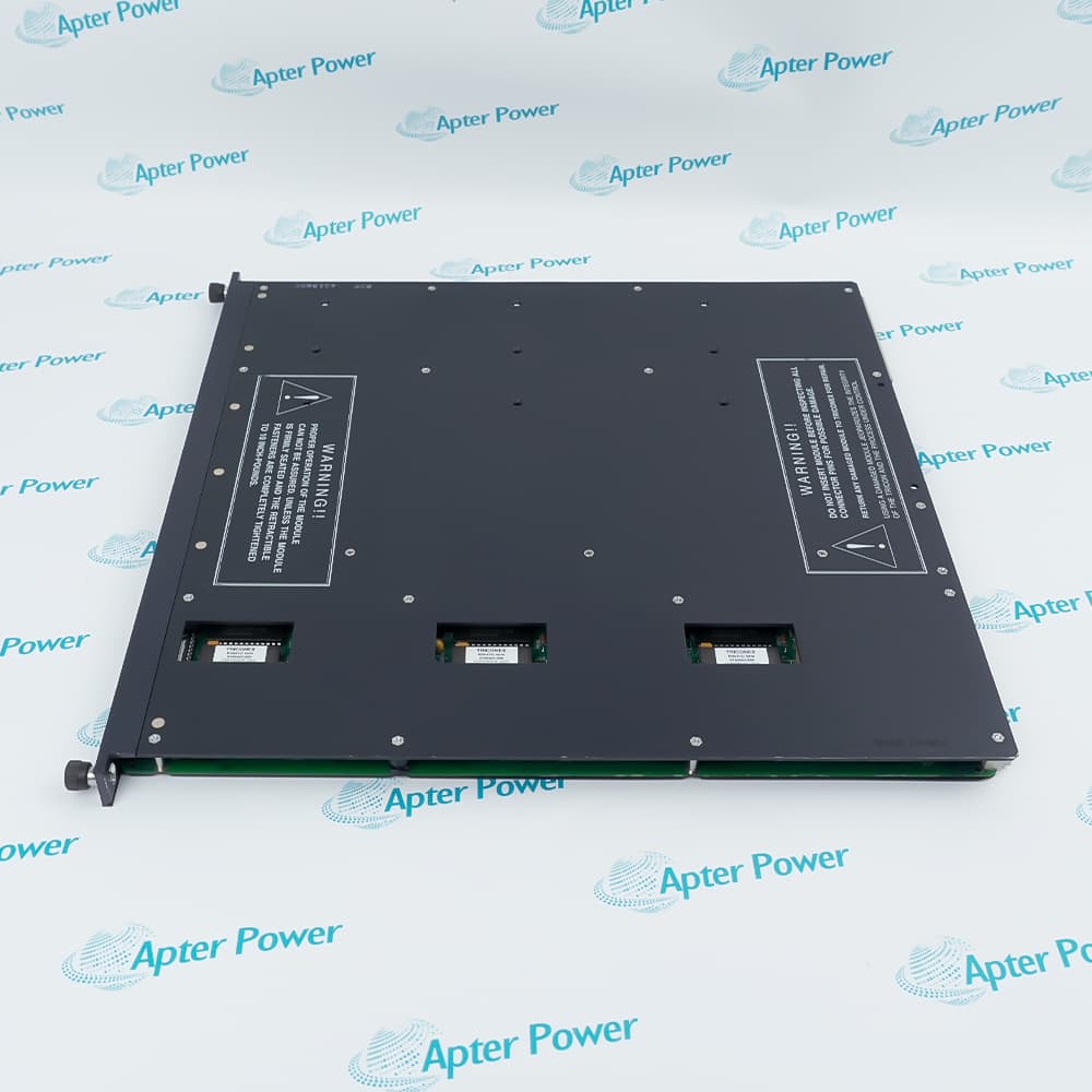
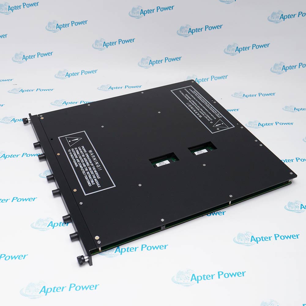
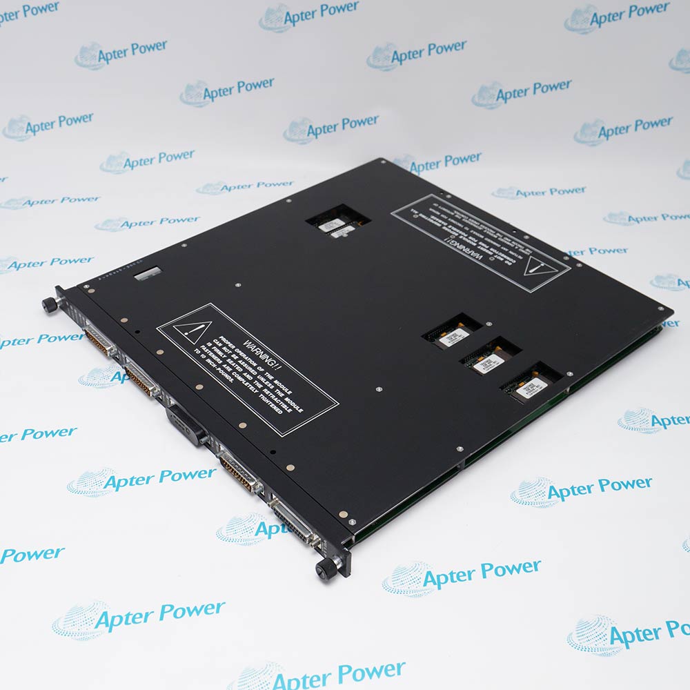
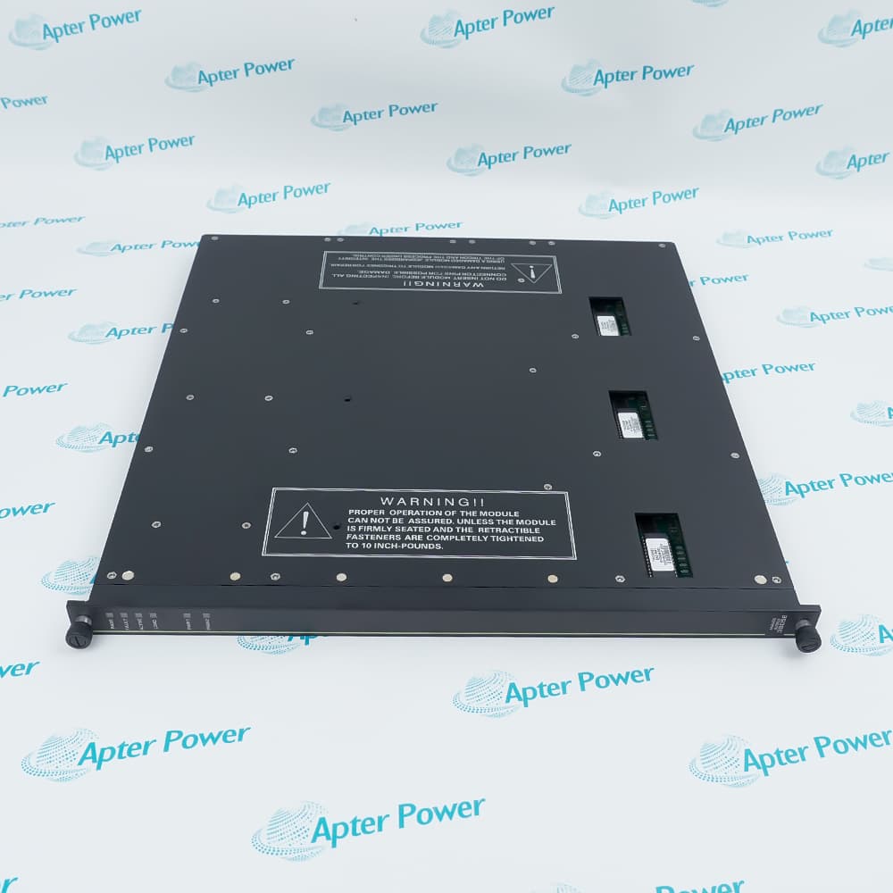
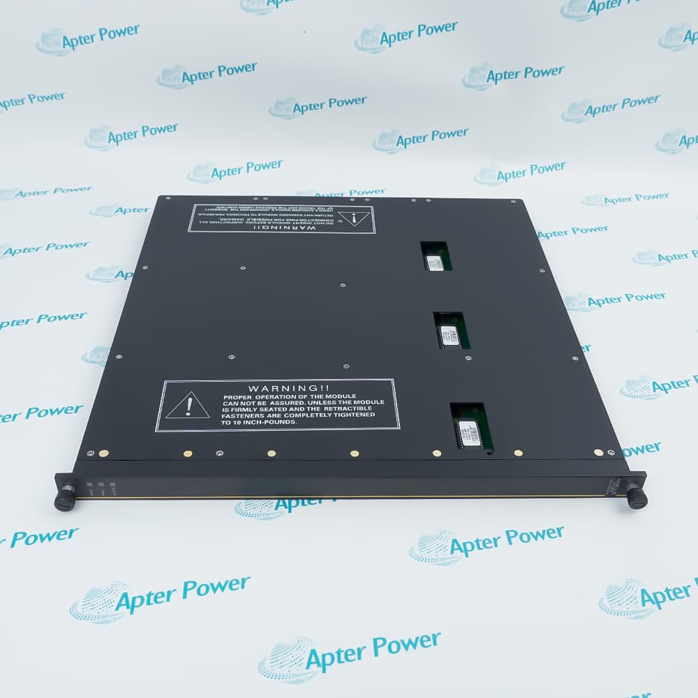
The 3008 Main Processor is available for Tricon v9.6 and later systems. Three MPs are installed in the main chassis, and each MP independently communicates with its I/O subsystem and executes the user-written control program. Key specifications include Motorola MPC860, 32-bit, 50 MHz processing, 16 MB DRAM, 32 KB battery-backed SRAM, 6 MB Flash PROM, and 25 Mbps TriBus communication.
Before replacement, collect these details:
Controller system version
Main chassis model, commonly 8110 in many legacy racks
Failed processor slot and channel
3008 part number, revision, and serial number
Current LED states
Diagnostic messages and event timestamps
Redundant power module status, such as 8311 where installed
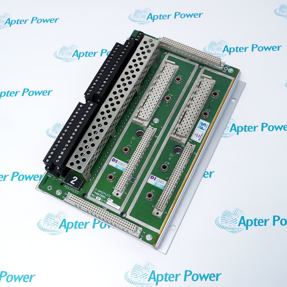
Related I/O alarms, especially 3503E DI, 3625 DO, and 3721 AI modules
Current application backup and engineering station access
A petrochemical example shows the value of this sequence. One plant saw FAULT on processor B during steady operation. Processor A and processor C remained PASS and ACTIVE. The first technician wanted to replace the module immediately because the spare was already in the cabinet. The lead engineer delayed the action for ten minutes to check the alarm summary, I/O bus messages, and power module status. That pause found no secondary faults, so the team proceeded safely. The replacement MP joined the running system, alarms cleared, and production continued without rate reduction.
Step-by-Step Hot Swapping Procedures
Use the following workflow as a field planning reference. It does not replace the local safety manual, work permit, MOC process, or approved controller procedure.
1. Freeze Nonessential Process Changes
Tell operations to avoid planned transitions during the replacement window. No feed switch, burner adjustment, compressor sequencing, proof test, or trip reset should overlap the work.
2. Confirm the Faulted Channel
Record the physical slot, channel, LED state, alarm message, and diagnostic time. Ask a second qualified person to confirm the same module before any hardware is touched.
3. Verify Two-Channel Health
The task should proceed only when the remaining two channels are stable and communicating. If another MP has a warning, intermittent fault, or synchronization issue, stop the job.
4. Validate the Spare Module
Check the 3008 label, revision, storage condition, and antistatic packaging. A spare request should include the installed model and revision, plus related rack parts if the plant is building a broader emergency kit, such as 8110 Main Chassis, 8311 Power Module, 3503E Digital Input Module, 3625 Digital Output Module, and 3721 Analog Input Module.
Apter Power can support teams looking for hard-to-find or obsolete automation spares across legacy control platforms, especially when a maintenance team needs correct module identification before an online intervention.
5. Set Permit and Bypass Controls
Apply maintenance bypasses only when required by the approved procedure. Every bypass needs a named owner, reason, approval time, expected clearance time, and operator visibility.
6. Remove the Faulted Processor
Use ESD protection. Loosen the retaining hardware. Pull the module straight out without disturbing adjacent MPs, power supplies, communication modules, or I/O wiring.
7. Insert the Replacement Processor
Seat the replacement evenly and firmly. Follow the specified fastener torque where the site procedure requires it. For many rack modules, proper seating and fastener tightening help prevent contact-related faults after insertion.
8. Hold the Work Area
Do not close the cabinet immediately. Watch the LEDs, check for new alarms, and confirm the processor progresses through diagnostics.
9. Confirm System Recovery
Use the engineering station or approved diagnostic tool to verify MP health, scan status, synchronization, and cleared alarms.
10. Close With Evidence
Record the failed module serial number, replacement module details, final LED status, diagnostic result, bypass removal time, and any follow-up recommendation.
Automatic State Alignment After Replacement
After insertion, the replacement MP must pass diagnostics, communicate over TriBus, and align with the active controller state. The system should return to full TMR operation when the replacement module is compatible, the backplane connection is sound, and no hidden system fault remains.
Do not judge success by one LED alone. A practical acceptance check should include:
Acceptance Point
Expected Result
PASS LED
On after diagnostics complete
FAULT LED
Off after successful recovery
ACTIVE LED
Matches expected processor role
Engineering diagnostics
No active MP fault
Chassis alarm
Cleared or explained
Process response
No output disturbance, no unexpected alarm burst
Bypass status
Removed, documented, confirmed by operations
If the new module remains faulted, likely causes include incorrect revision, poor seating, damaged backplane connector, unresolved power issue, communication problem, or a system fault misdiagnosed as processor failure.
Common Triconex 3008 & I/O Module Failure Signatures
A good fault response separates three layers of evidence: local LEDs, diagnostic records, and field behavior. The phrase Triconex 3008 LED diagnostic codes is useful for search, but LEDs and diagnostic codes are separate evidence types. LEDs help the technician identify the local condition. Diagnostic tools confirm the fault path.
Fault LED / Diagnostic Code Quick Reference
LED, Alarm, Or Symptom
Likely Meaning
Field Check
PASS on
Module passed self-diagnostics
Confirm normal channel status
FAULT on
Module fault detected, replacement may be required
Verify diagnostics before removal
ACTIVE on
Module is executing the user-written control program
Compare with expected processor role
MAINT1 or MAINT2 on
Maintenance indicator active
Check diagnostic tool and local procedure
COM TX / COM RX active
Communication bus activity
Review communication alarms if abnormal
I/O TX / I/O RX active
I/O bus activity
Check I/O bus status and module alarms
Chassis alarm
System integrity alarm active
Identify source before hardware action
DO Load/Fuse alarm
Field load, fuse, output circuit, or wiring issue
Inspect field loop before module replacement
Repeated I/O FAULT
Channel or module diagnostic issue
Check point diagnostics and hot-spare status
New fault after insertion
Seating, revision, backplane, power, or wider system issue
Stop and review before second replacement
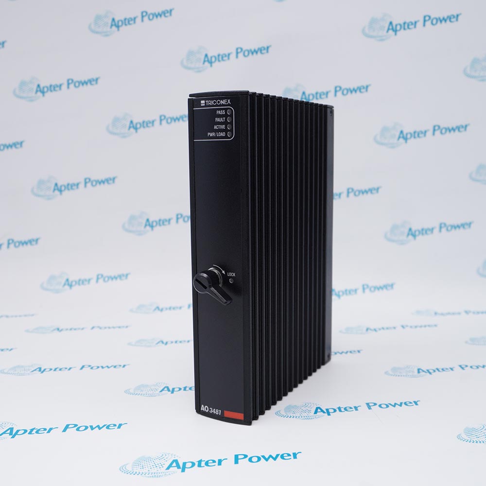
The 3008 indicators include PASS, FAULT, ACTIVE, MAINT1, MAINT2, COM TX/RX, and I/O TX/RX. PASS means the module has passed self-diagnostic tests, FAULT means the module has a fault and should be replaced, and ACTIVE means the module is executing the user-written control program.
For Troubleshooting Triconex I/O module failures, the most important habit is to avoid replacing modules before checking the field circuit. Output module diagnostics can identify field-wiring problems, and intelligent I/O modules can report faults that originate outside the module body.
A batch plant case illustrates the point. A 3625 DO module produced repeated load alarms during washdown periods. The maintenance team replaced the output module once, and the same alarm returned two weeks later. A loop check found moisture-related leakage in the solenoid junction box. The module was reporting a real field problem. It was not the failed asset.
A second case involved a 3503E DI module that showed intermittent fault indications after cabinet work. The root cause was a loose termination connection introduced during unrelated wiring cleanup. The lesson for I/O faults is simple: confirm module health, field wiring, termination hardware, and process timing before ordering replacement parts.
Long-Term Reliability of Triple Redundant Controllers
The Triconex 3008 processor module lifespan should not be reduced to a single number. Field life depends on cabinet temperature, vibration, dust, corrosive gas exposure, power quality, grounding, handling practices, historical faults, and spare storage quality.
Good installation practice emphasizes controlled environmental conditions, including temperature, contaminants, shock and vibration, and electromagnetic interference. A controller should be located or isolated away from obvious heat sources, corrosive gases, dust, rotating machinery, and strong EMI sources.
For legacy racks, reliability planning should be module-specific:
Asset Area
Practical Reliability Action
3008 Main Processor
Track faults, revision, operating history, and spare availability
Confirm communication health and compatibility before outage work
One offshore utility system had no recent processor failures, so the spare budget was repeatedly postponed. The cabinet, however, sat close to a compressor package and logged recurring high-temperature alarms during summer. When one MP finally faulted, the purchasing team had to source a replacement under time pressure. The technical failure was manageable. The spare strategy created the stress.
This is where Apter Power fits into the maintenance cycle: helping teams source hard-to-find or obsolete automation spares before a minor hardware fault turns into a production event.
Maximize Your Uptime With Fault-Tolerant Control Strategies
A controlled hot swap is the final action. The stronger strategy begins months earlier.
For plants running legacy safety systems, the uptime program should include:
A live installed-base register by rack, slot, model, revision, and serial number
A tested critical-spare list covering 3008, 8110, 8311, 3503E, 3625, 3721, 4351B, and 4329
A diagnostic capture template for PASS, FAULT, ACTIVE, COM, and I/O indicators
A Go/No-Go checklist for online processor replacement
A bypass approval log with restoration verification
A post-maintenance review after every processor or I/O replacement
A quarterly review of cabinet temperature, power events, grounding, and vibration exposure
A power plant case shows the business impact. Two similar safety racks supported turbine auxiliary systems. Rack 1 had a validated spare kit with a 3008 MP, 8311 power module, and key I/O modules. Rack 2 had no verified spare. When both racks later developed separate hardware alarms, Rack 1 was restored during a short controlled window. Rack 2 stayed under increased monitoring while procurement searched for a compatible part.
The engineering skill on both racks was similar. The recovery time was different because the spare strategy was different.
For B2B maintenance teams, processor replacement planning should connect engineering and procurement. A purchase request should include the failed module, rack context, required revision, urgency, and adjacent spares that may affect recovery. Apter Power can support that conversation for legacy automation parts, especially when the plant needs a practical path around long lead times for discontinued hardware.
FAQs
Q1. Do I need to shut down the process to replace a Triconex I/O module?
Usually, no, if the system is healthy and the site procedure permits online maintenance. Each I/O slot can contain two identical modules, and the control can switch to a healthy module if a fault is detected. A faulty module can also be replaced online by inserting a healthy module in the spare slot, switching control to it, and removing the faulty one.
Q2. How does the system notify operators when a single processor fails?
Operators usually see a chassis or system integrity alarm. Maintenance personnel then confirm the local processor LEDs and diagnostic records. A FAULT LED on one MP points to the affected channel, but the team should still check power, communication, and I/O alarms before replacement.
Q3. What is the lifespan of a Triconex 3008 module under normal conditions?
There is no universal field lifespan for a 3008 processor. A clean, cool, stable cabinet can support a long service life. Heat, vibration, poor power quality, corrosive atmosphere, repeated handling, and poor spare storage can shorten reliability. Use condition history and installed-base review for planning.
Q4. Can firmware updates be performed without stopping the controller?
Firmware and version work needs stricter planning than a like-for-like hardware swap. Some online work may be possible under defined system conditions, but engineering must confirm version compatibility, project backup quality, keyswitch status, access rights, and rollback planning before any change.
Q5. How do redundant power supplies interact with the TMR architecture?
The processing channels are triplicated, while the power modules are dual-redundant. A power module issue may allow operation to continue, but it reduces the margin available during maintenance. Any power alarm should be reviewed before processor replacement because unstable chassis power can create misleading diagnostics.
Q6. What software or engineering station access is required for online processor replacement?
The team should have approved diagnostic access to MP health, chassis alarms, application status, and synchronization status. The current project backup, system version, node settings, and communication path should be available before the cabinet is opened.
Q7. How does a maintenance bypass affect the safety integrity level during hot swap?
A bypass reduces the active protection available for the covered function while it is applied. Use the narrowest bypass allowed by the approved procedure, make it visible to operations, assign an owner, set a time limit, document the reason, and confirm removal after the replacement is verified.
Reliable Maintenance Strategies for Triconex Systems
Maintaining System Availability During Hardware Faults
Legacy safety systems are designed to tolerate single-channel failures, allowing maintenance activities to be performed without immediately affecting production. Proper replacement procedures and healthy redundancy help plants maintain safe and stable operation while restoring full protection capability:
Online Processor Replacement for Continuous Operation
The Triconex 3008 Main Processor can be replaced online in many TMR systems when two processor channels remain healthy. Together with components such as the 8110 Main Chassis and 8311 Power Module, the architecture helps maintain process continuity during maintenance activities. This approach minimizes unplanned downtime and reduces the impact of hardware failures on production.
Strategic Spare and Module Management
Long-term reliability depends on effective diagnostics and proper spare planning. Critical modules, including the 3503E Digital Input Module, 3625 Digital Output Module, 3721 Analog Input Module, 4351B TCM, and 4329 NCM, should be monitored and managed proactively. Maintaining verified spare inventories enables faster recovery, reduces emergency procurement, and improves the availability of legacy Triconex safety systems.







Leave Your Comment