How to Design a Bently 3500 System Redundant Protection Architecture for Steam Turbines and Compressors
About the author
Written by May, Managing Director of Apter Power
May's Facebook:
May has been working at Apter Power for 10 years, where she turns complex power-automation challenges into clear, executable plans.
Drawing on deep product knowledge and field-proven methodologies, she has already supported 2 000+ customers in over 100 countries, maintaining a 96 % satisfaction score.
A steam turbine or compressor protection scheme is judged in a few seconds when the machine moves from stable operation into rising mechanical risk. At that point, the plant needs clear measurement, a dependable shutdown path, and enough evidence to understand what happened. A Bently 3500 system can support that role well when the design is built around actual failure modes, clear trip philosophy, and plant maintenance reality rather than a generic channel list.
What Protection Objectives Should a Bently 3500 System Meet for Steam Turbines and Compressors
A protection system for critical rotating equipment should achieve three objectives. It should detect developing mechanical distress before damage occurs, trigger a shutdown when safe operating limits have been exceeded, and preserve data that helps the site diagnose the event afterward.
For a steam turbine, the main concerns usually include rising shaft vibration, axial movement, thermal growth mismatch, unstable startup behavior, and speed-related risk. For a centrifugal compressor, the same rotor-related variables matter, though casing response, seal condition, lube oil quality, and process disturbances often play a larger role in how a fault develops. That is why a Bently 3500 system should be designed as a machine protection layer with diagnostic value built into it.
Typical Failure Modes
Steam turbines and compressors share some protection principles, though their failure patterns are not identical. A turbine train usually needs tighter attention to shaft vibration, axial position, phase reference, and thermal movement. A compressor train often needs the same core rotor coverage plus stronger attention to casing vibration, seal distress, and lubrication-related degradation.
That difference shows up clearly in plant experience. In one boiler feedwater pump turbine case, a sharp change in 1X response suggested a serious rotor problem, yet the actual cause was a loosened coupling component. In a compressor train, rising vibration and changing orbit behavior may initially look like a rotor dynamic issue, while the real driver is rub linked to seal damage, dirty oil, or excessive filter differential pressure. The protection design has to detect the event and help the plant separate cause from symptom.
How to Select the Right Bently 3500 Hardware Platform and Modules
Hardware selection should follow machine duty, shutdown philosophy, and maintenance practice. When those three factors are aligned, the rack becomes easier to commission, easier to troubleshoot, and easier to trust during a startup or upset.
Rack Layout
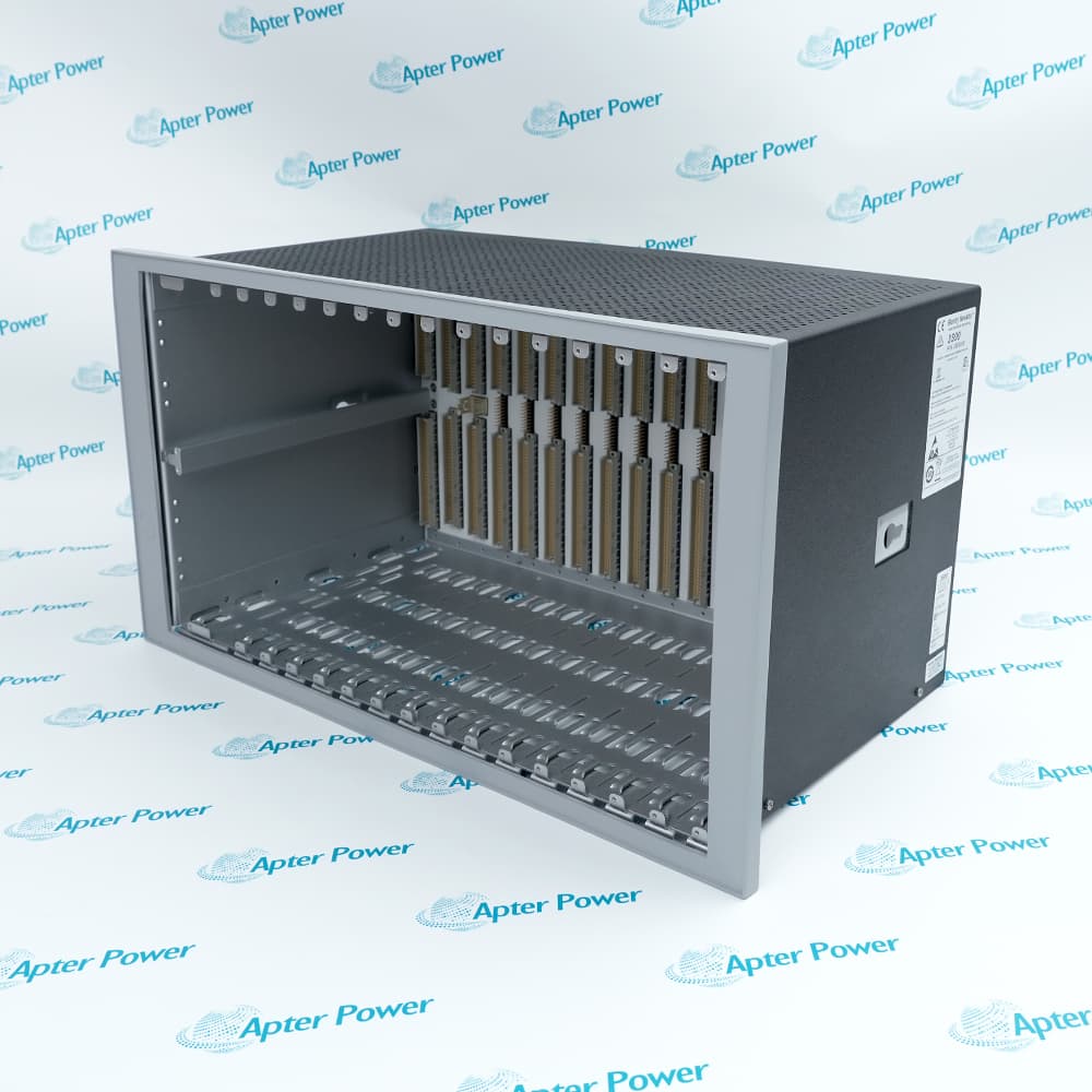
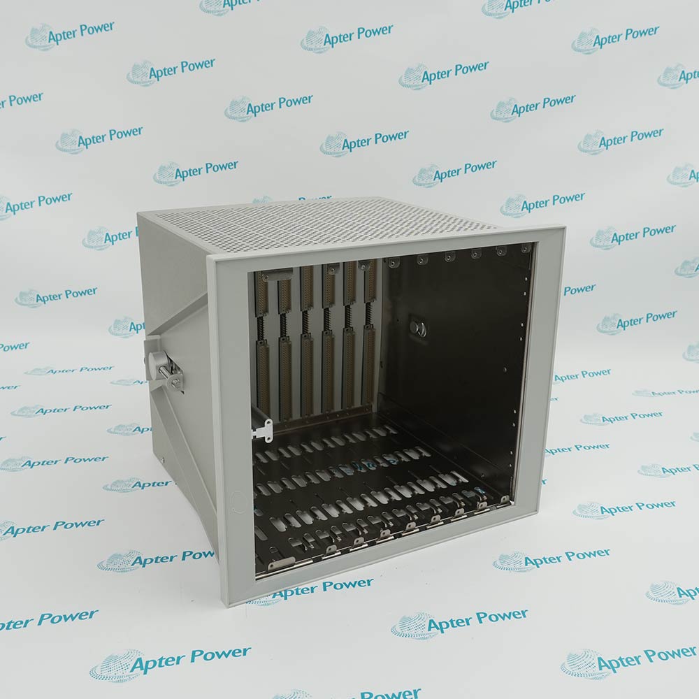
For most turbine and compressor trains, a full rack is the better choice. It gives the site room for relay segregation, future expansion channels, extra diagnostics, and cleaner marshalling. Smaller rack options can work in tight retrofits, though they often become restrictive once the plant wants clearer annunciation or more position and vibration channels.
The rack should also preserve a clean boundary between protection and access. Configuration, display, and communications are important, though they should not be treated as part of the shutdown path. In practice, that means the protection decision stays inside the rack logic, while networked systems serve operators, historians, and maintenance staff.
Signal Coverage
Signal selection should follow the failure mechanisms the plant is actually trying to control.
Add thermal context around bearings and auxiliaries
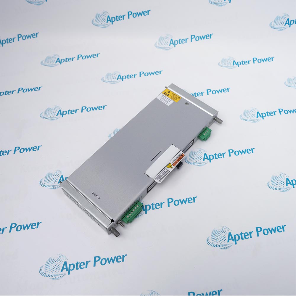
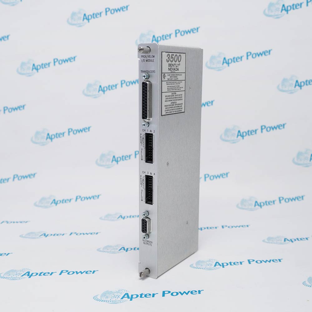
In many steam turbine applications, a proximity monitor such as 3500/40M paired with a position monitor gives a strong core protection set. On compressors, the same base arrangement often works well, with additional attention given to casing response and supporting process context.
One design boundary should remain clear. Speed monitoring inside a Bently 3500 system is useful for indication and diagnostics. Overspeed trip protection should remain in its own independent layer.
How to Configure Redundant Power Supplies and Rack Architecture in a Bently 3500 System
Redundancy is only meaningful when the failure paths are genuinely separate. Two power supplies that share the same breaker, the same terminal bottleneck, or the same vulnerable distribution point may look redundant on paper and still fail together in service.
Power Design
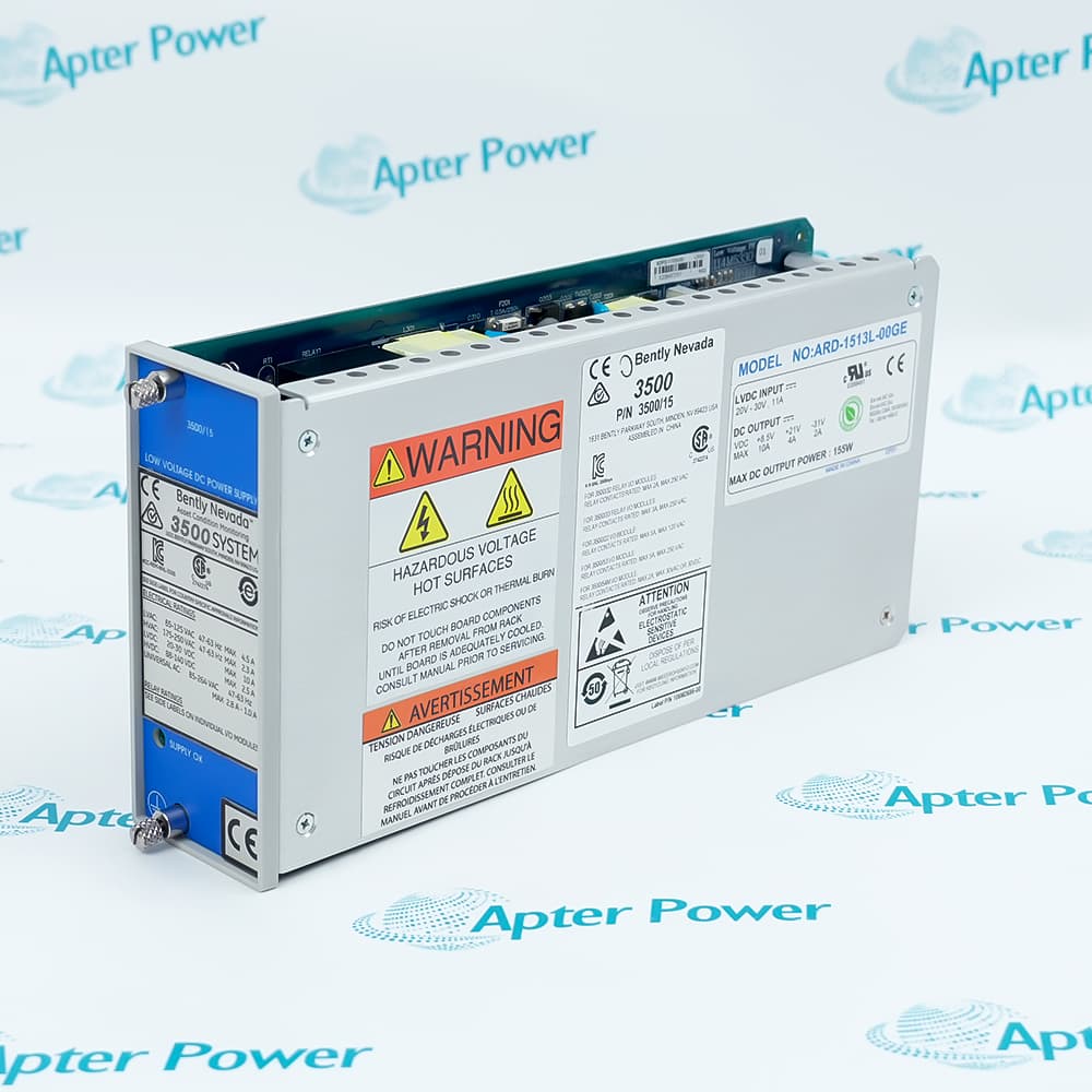
A sound Bently 3500 redundant power supply configuration usually follows a simple pattern. The primary feed comes from the normal instrument source, while the backup feed comes from an electrically independent source, often UPS-backed. Loss of either source should alarm into the DCS, but trip logic and relay execution should remain inside the protection system.
That arrangement gives operations visibility during a degrading power condition without moving shutdown authority into a control layer that was never meant to own machine protection.
Rack Arrangement
Rack arrangement should also support maintenance and fault isolation. Shutdown relays, alarm relays, and communication functions should not be mixed casually. Wiring should let technicians isolate a bad input or a questionable field contact without disturbing unrelated functions.
This sounds like a detail, though it matters during outages. Plants lose time when drawings are unclear, relay assignments are crowded together, or spare capacity is removed to save cabinet space on day one. A disciplined rack architecture makes testing faster and future modifications safer.
How to Design Voting Logic and Trip Circuits for Reliable Shutdown
Trip reliability depends on relay philosophy as much as on sensor quality. In many plants, shutdown problems are caused less by a failed probe and more by ambiguous voting logic, mixed alarm and trip contacts, unmanaged bypasses, or incomplete field testing after a turnaround.
Relay Strategy
A Bently 3500 system can support relay-based shutdown architecture effectively when each output has one defined purpose, and each logic path can be reviewed without confusion. For larger trains, a relay module such as 3500/33 is often used to keep shutdown outputs separate from routine alarm handling.
The most reliable voting philosophy is usually the simplest one:
Use a direct trip where one variable clearly indicates a destructive condition.
Use voting only when multiple channels are intentionally monitoring the same risk.
Keep alarm relays and shutdown relays separate.
Manage bypasses with authority, time limits, and event recording.
This structure makes trip behavior easier to explain during management of change reviews, trip investigations, and turnaround audits.
Field Execution
Trip circuits often fail quietly. A sticky bypass key, a degraded relay contact, moisture in a marshalling cabinet, or undocumented field changes can weaken shutdown integrity while the software view still appears normal.
That is why trip path validation should cover the full chain. The plant should prove rack output, field contact transfer, final shutdown device response, and first-out reporting together. For teams dealing with trip circuit problems, the fastest route is to compare approved cause and effect, live relay behavior, and field response side by side.
Coordinating Main Protection and Backup Protection for Critical Machinery
Main and backup protection should support the same machine philosophy while staying independent where it matters most. On a steam turbine, the main mechanical layer often centers on shaft vibration, axial position, and thermal growth-related channels inside the Bently 3500 system, while overspeed remains independent. On a centrifugal compressor, the main mechanical layer usually focuses on radial vibration and thrust position, while the backup side may depend on driver trips, lube oil permissives, seal system protection, or process shutdowns.
Protection Roles
This division works best when each layer has a defined role. The main protection layer detects direct machine distress. The backup layer covers related risks that can quickly damage the train. Control systems provide context and operator visibility. Maintenance records preserve the event history and the inspection trail.
The benefit becomes obvious in real plant situations. A turbine event with an abnormal 1X response may require the site to decide quickly between coupling inspection, balance review, rotor work, or expansion assessment. A compressor event associated with rub and seal distress demands a different response, one that links vibration evidence to oil cleanliness, filter differential pressure, and seal condition. The protection architecture should support those decisions instead of leaving each department with only part of the story.
How to Validate and Maintain a Redundant Bently 3500 Protection Design Over Its Lifecycle
Commissioning quality shapes long-term confidence. A rack that is configured quickly and only partially proved may remain in service for years while quietly carrying avoidable weaknesses.
Commissioning
A practical FAT and SAT sequence should include:
channel scaling and engineering units
alert and danger setpoints
relay action and first-out reporting
loss of primary power and transfer to backup power
final shutdown device response
DCS alarm mapping
bypass behavior and restoration steps
Treating these checks as one sequence is important. Plants that only test wiring point by point often miss the interaction between logic, relay action, and final device behavior.
Lifecycle Maintenance
Over time, the weak points are usually small and gradual. Probe gaps drift. Terminal quality changes after repeated outage work. Bypass records become incomplete. Relay outputs may still change state in software while field loads deteriorate.
Useful lifecycle tasks include periodic proof testing, review of event history after every trip or startup upset, outage inspection of probe systems and marshalling points, and verification that as-found logic still matches the approved cause and effect. A Bently 3500 system stays valuable when the plant treats it as a living protection layer rather than a rack that was finished at commissioning and forgotten.
Putting Bently 3500 Protection Design into Practice
A strong protection design is specific to the machine, specific to the shutdown philosophy, and specific to the way the plant maintains its equipment. Measurements should match failure modes. Redundant power should be truly independent. Voting logic should stay simple enough to prove. Main and backup layers should be separated with intent. When a Bently 3500 system is applied that way, it gives operations a shutdown path they can trust and gives maintenance evidence they can use during the next startup, trip review, or turnaround.
FAQs
Q1. Can a Bently 3500 system send data directly to a DCS or historian?
Yes. The 3500/92Communication Gateway is built for that job and supports Ethernet TCP/IP plus serial communications. It can transfer monitored values and status data to control systems, historians, and plant computers without interfering with protection functions.
Q2. How is hazardous-area transducer wiring handled in a 3500 installation?
The usual solution is to use 3500/04 Internal Barriers. These provide intrinsically safe interfaces for transducer systems connected directly to the 3500 rack, giving explosion protection while remaining fully compatible with the protection system architecture.
Q3. Which module should be added when lube oil pressure, seal gas pressure, or level must be monitored with machinery data?
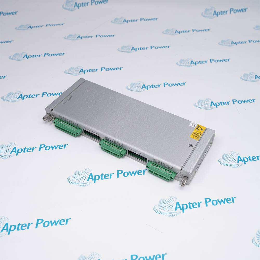
The 3500/62 Process Variable Monitor is intended for that purpose. It accepts 4 to 20 mA current inputs and proportional voltage inputs, making it suitable for pressures, flows, temperatures, and levels that merit continuous monitoring.
Q4. Can operators view rack status locally without relying on the DCS?
Yes. The 3500/94MVGA Display Module can show system events, alarm events, module and channel data, alarm and OK status, plus custom display screens. That is useful during startup checks, troubleshooting, and local walkdowns.
Q5. What module fits applications such as valve position, differential expansion, or case expansion?
The 3500/45 Position Monitor is the right fit for those duties. It accepts proximity transducers, RPTs, AC and DC LVDTs, and rotary potentiometers, then conditions those inputs and compares them with user-programmable alarm setpoints.
Core Protection Philosophy and Failure Mode Analysis
A well-designed Bently 3500 protection system must address three fundamental objectives: early detection of mechanical distress, reliable shutdown triggering when safe limits are exceeded, and comprehensive data preservation for post-event diagnosis. While steam turbines and compressors share common rotor-related monitoring needs—such as shaft vibration, axial position, and phase reference—they exhibit distinct failure patterns. Steam turbines demand closer attention to thermal growth mismatch and startup instability, whereas compressors require enhanced monitoring of casing response, seal condition, and lubrication quality.
Hardware Architecture
Effective hardware selection centers on machine duty, shutdown philosophy, and maintenance accessibility. Full rack configurations are preferred for critical trains, providing adequate space for relay segregation, future expansion, and clean marshalling boundaries between protection and communication functions.
Redundancy Implementation
True redundancy requires electrically independent power sources—typically normal instrument power paired with UPS-backed backup—ensuring trip logic remains autonomous even during power degradation. Signal coverage should align with specific failure mechanisms, utilizing proximity probes for shaft dynamics, LVDTs for thermal expansion monitoring, and process variable modules for auxiliary parameters like lube oil pressure. Critically, speed indication within the 3500 system serves diagnostic purposes only; overspeed protection must remain in an independent layer.






Leave Your Comment