LOCON 24-0360-A32I
LOCON 24-0360-A32I
LOCON 24-0360-A32I
LOCON 24-0360-A32I
LOCON 24-0360-A32I
LOCON 24-0360-A32I
Ask our team:
  • Phone: +86 181 0690 9650
  • E-Mail sales1@apterpower.com
  • Lifecycle status

    Discontinued / Obsolete by OEM
    For Deutschmann LOCON 24-0360-A32I, Apter Power provides quotations, manuals and configuration-selection assistance.

LOCON 24-0360-A32I

/ 4.9
1001 reviews | Need a Specific Revision?
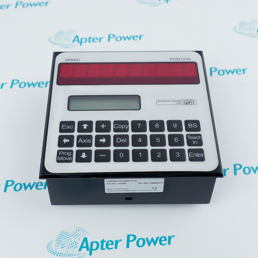
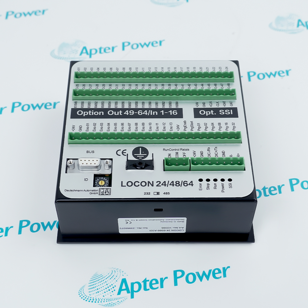
Deutschmann LOCON 24-0360-A32I is a LOCON 24 electronic cam controller that evaluates a 360-increment parallel absolute encoder and controls 32 outputs with bitwise idle-time compensation.
In Stock
Ships by Wednesday, October 28
Fast Shipping Available
Get a quick price for LOCON 24-0360-A32I
Quantity
*E-mail
Company
*Mobile
*Content
Upload (gif, jpg, jpeg, png, bmp, doc, docx, xls, xlsx, ppt, pdf, csv)

Technical specifications for LOCON 24-0360-A32I

  • Manufacturer:
    Deutschmann
  • Part Number:
    LOCON 24-0360-A32I
  • Product Family:
    LOCON 24 Cam Controls
  • Product Type:
    Electronic Cam Controller
  • Stock:
    1
  • Encoder Interface:
    Parallel absolute encoder
  • Encoder Resolution:
    360 increments per revolution
  • Output Expansion:
    32 outputs
  • Idle-Time Compensation:
    Bitwise
  • Supply Voltage:
    24 VDC ±20%
  • Logic Input:
    24 VDC, maximum 10 mA
  • Output Stage:
    24 VDC PNP, 0.3 A
  • Output Group Limit:
    1 A per block of eight outputs
  • Weight:
    2.09 lbs (0.95 kg)
  • Estimated shipping dimensions:
    14.5×14.5×6.8 cm
  • Tariff Code:
    8537101190
  • Country of origin:
    Germany
  • Place of shipment:
    Xiamen,Fujian,China
By purchasing this item, you agree to the Terms & Conditions, ApterPower is not an authorized distributor for listed manufacturers or tradenames and therefore the manufacturer's warranty does not apply. All our products come with ApterPower's 1-year warranty.

More Information

Overview Manuals Position Logic Output Protection Cam Programming Operating Control

Features:

  • Interprets 360-position data from a parallel absolute encoder.
  • Expands the LOCON 24 platform to thirty-two switching outputs.
  • Applies idle-time compensation separately to individual output bits.
LOCON 24-0360-A32I links programmed cam positions to solid-state output channels rather than mechanical cam tracks.

The order code fixes the encoder resolution, output expansion and timing-compensation arrangement for this configuration.

Output-state indicators and run control provide operating feedback without combining those functions with the position-input wiring.

The Deutschmann LOCON 24-0360-A32I Electronic Cam Controller may still be available for purchase and support from Apter Power beyond End-Of-Life (EOL) by the manufacturer (OEM).
Deutschmann LOCON 24-0360-A32I Electronic Cam Controller Manuals,Datasheets,Link Important Notice: Other accessories, manuals, cables, calibration data, software, etc. are not included with this equipment unless listed in the above stock item description. All prices are shown in USD.

Encoder and Position Data

  • Encoder Type: Parallel absolute shaft encoder.
  • Resolution: 360 increments per revolution.
  • Position Basis: Programmed switch points are evaluated against the actual encoder value.
  • Speed Relation: Idle-time correction shifts output timing relative to motion.

Output Safeguards

  • Short Circuit: The PNP output stages include short-circuit protection.
  • Sustained Overload: Affected output transistors remain disabled until power is cycled.
  • Channel Status: Output LEDs show the switching state of individual channels.
  • Grouped Load: Each block of eight outputs is limited to a combined 1 A.

Cam Program Structure

  • Switch Points: Each output is assigned programmed switch-on and switch-off positions.
  • Channel Timing: Idle-time compensation is configured separately by output bit.
  • Output Expansion: Code A32 defines the thirty-two-output arrangement.
  • Parallel Channels: Up to three outputs require identical switch points when connected together.

Operating Functions

  • Run Control: The controller includes a run-control relay function.
  • Logic Inputs: External control inputs operate at 24 VDC with a maximum 10 mA input current.
  • Output Level: Each solid-state channel supplies a 24 V PNP output rated at 0.3 A.
  • Power Input: The controller operates from 24 VDC with a ±20 percent tolerance.
Description
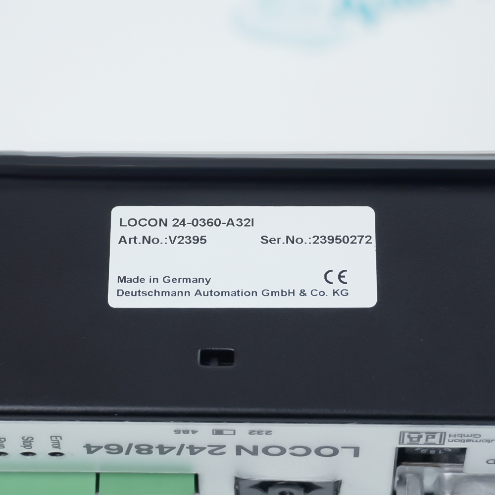
Deutschmann LOCON 24-0360-A32I is an electronic cam controller in the LOCON 24 family. Its order code combines a parallel absolute-encoder version with 360 increments per revolution, the A32 expansion for 32 outputs and bitwise idle-time compensation.

Position information enters LOCON 24-0360-A32I through the parallel absolute-encoder interface and becomes the reference for programmed switch points. The controller relates those positions to individual output channels, while the idle-time compensation option offsets switching for the response time of the connected process.

Field outputs on LOCON 24-0360-A32I are 24 V PNP stages rated at 0.3 A each, with a combined limit of 1 A for every block of eight outputs. The output transistors are short-circuit protected and remain disabled after a sustained overload until the supply is switched off and on again.

Operation of LOCON 24-0360-A32I includes output-state indication, program and switch-point handling, and a run-control function. Up to three outputs may be connected in parallel only when their programmed switch-on and switch-off points are identical.
Alternative Names
Deutschmann 24-0360-A32I LOCON 24 O360 A32 I LOCON24-0360-A32I Deutschmann LOCON 24 O360 A32I LOCON 24-O360-A32I LOCON 24 360 32-output Cam Control Deutschmann Automation LOCON 24-0360-A32I L0CON 24-0360-A32I
Technical notes
Deutschmann LOCON 24-0360-A32I permits up to three output channels in parallel only when their programmed switch-on and switch-off points are identical.
Exceptional Service

Our Mission

  • 100% Satisfaction

    We believe expertise is priceless. With over 20 years of experience, and top engineers on staff, we can help you solve or avoid problems that threaten your business.
  • Trust Guaranteed

    Not only do we have a vast inventory, our team makes sure every piece of equipment is in working condition. Your purchases are also backed by our Warranty.
  • Expertise

    Time is money, especially when your equipment is down. We work quickly to get your equipment on its way so you can get it back up and running.

FAQS

The following is a list of questions commonly asked by our customers. Please contact us if you have a question about our process that is not answered below.
Why can LOCON 24-0360-A32I switch at the wrong mechanical position when machine speed changes?
LOCON 24-0360-A32I includes bitwise idle-time compensation; the compensation value must correspond to the response time of the channel whose switch point is drifting.
What should be checked when one output block on LOCON 24-0360-A32I repeatedly shuts down?
The connected loads on LOCON 24-0360-A32I must stay within 0.3 A per output and 1 A for each block of eight outputs; a sustained overload disables the output transistors until the supply is cycled.
Can several LOCON 24-0360-A32I outputs be paralleled for a higher load?
A maximum of three LOCON 24-0360-A32I outputs may be connected in parallel, and those channels must use identical switch-on and switch-off points.
How should an incorrect position count on LOCON 24-0360-A32I be isolated?
Confirm that the encoder presented to LOCON 24-0360-A32I is the parallel absolute type with 360 increments per revolution, then compare the received position with the programmed switching positions.
Why might the status indication on LOCON 24-0360-A32I change while the field device remains inactive?
An indicated channel can still lack usable field current; for LOCON 24-0360-A32I, verify the 24 V output supply, the channel load and any overload condition before changing the program.
What can prevent LOCON 24-0360-A32I from entering the intended run state?
The run-control path and the selected program must both be valid for LOCON 24-0360-A32I; check the run input or relay function before altering stored switch points.