Ask our team:
  • Phone: +86 181 0690 9650
  • E-Mail sales1@apterpower.com
  • Lifecycle status

    Active / Available from OEM
    For DS200SDCCG1A, Apter Power can coordinate a quotation and access to authenticated General Electric technical documentation.

DS200SDCCG1A

/ 4.9
1001 reviews | Need a Specific Revision?
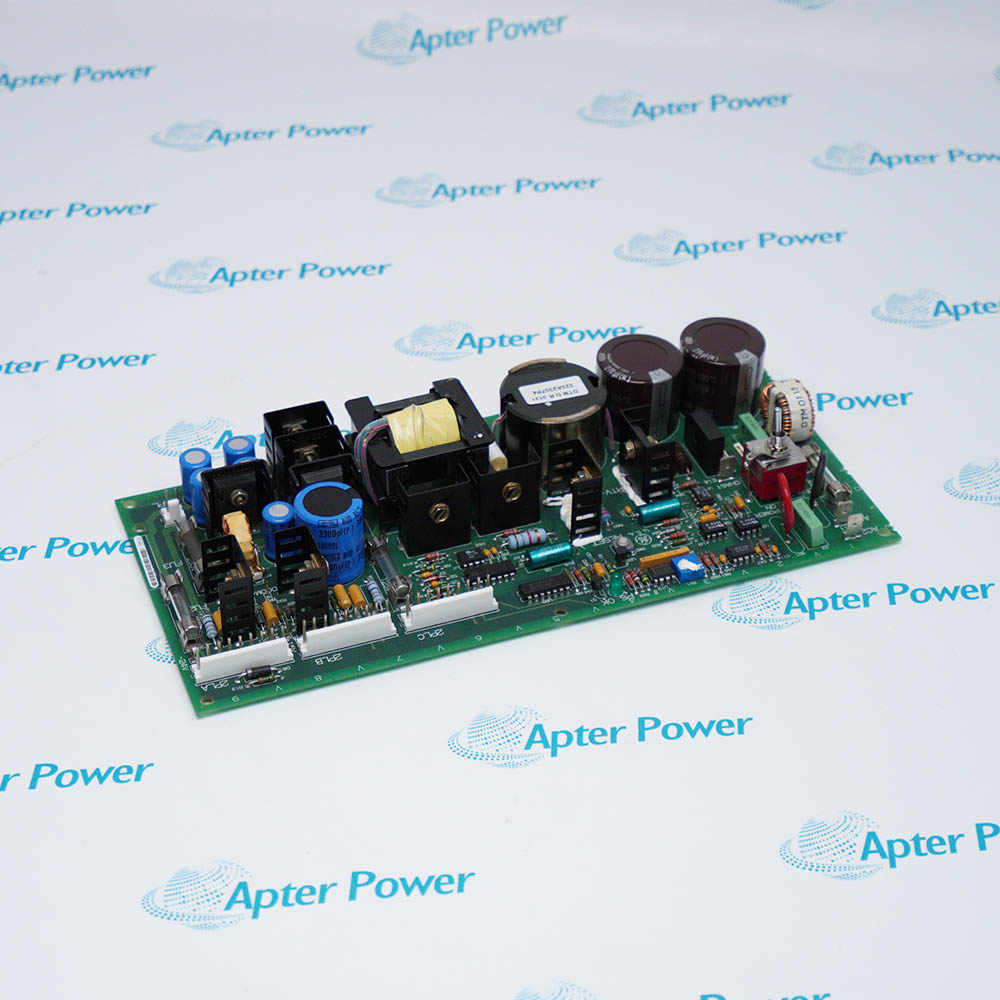
General Electric DS200SDCCG1A is the G1 SDCC drive control card with three coordinated processors for AC2000, DC2000, and EX2000 applications.
In Stock
Ships by Thursday, October 29
Fast Shipping Available
Get a quick price for DS200SDCCG1A
Quantity
*E-mail
Company
*Mobile
*Content
Upload (gif, jpg, jpeg, png, bmp, doc, docx, xls, xlsx, ppt, pdf, csv)

Technical specifications for DS200SDCCG1A

  • Manufacturer:
    General Electric
  • Part Number:
    DS200SDCCG1A
  • Product Family:
    GE Mark V/VI Driver Board
  • Product Type:
    Drive Control Card
  • Stock:
    1
  • Card Group:
    G1 SDCC
  • System Applications:
    AC2000, DC2000, and EX2000
  • Processor Count:
    Three 16-bit processors
  • Drive Processor:
    80C186 DCP
  • Interprocessor Memory:
    Dual-ported RAM
  • Diagnostic Indicators:
    Ten onboard LEDs
  • Configuration Hardware:
    JP and WJ jumpers
  • Tariff Code:
    8538900000
  • Country of origin:
    USA
  • Place of shipment:
    Xiamen,Fujian,China
By purchasing this item, you agree to the Terms & Conditions, ApterPower is not an authorized distributor for listed manufacturers or tradenames and therefore the manufacturer's warranty does not apply. All our products come with ApterPower's 1-year warranty.

More Information

Overview Manuals Diagnostics Processing Configuration Product Applications

Features:

  • Divides general drive, motor-loop, and calculation-intensive tasks among DCP, MCP, and CMP sections.
  • Exchanges data among the three processor sections through dual-ported RAM.
  • Presents documented normal and fault patterns through ten onboard diagnostic LEDs.
The DS200SDCCG1A is the fully featured G1 SDCC group identified for AC2000, DC2000, and EX2000 equipment. Group designation matters because other SDCC groups do not carry the same application scope.

Multiple plug connectors distribute power, serial communication, LAN, motor-control, and auxiliary-board signals. The layout also accepts documented option cards on the SDCC assembly through dedicated connectors and standoffs.

Processor resets can originate from control power, watchdog, local, or system paths. Reading the LED pattern together with testpoint and connector behavior helps separate a processor-section fault from an external interface problem.

Official General Electric documentation and a quotation for the DS200SDCCG1A Drive Control Card are available through Apter Power.
General Electric DS200SDCCG1A Drive Control Card Manuals, Datasheets, Links

Important Notice: Other accessories, manuals, cables, calibration data, software, etc. are not included with this equipment unless listed in the above stock item description.

SDCC LED and Reset Diagnostics

  • LED array: Ten onboard indicators present documented processor and board fault patterns.
  • Pattern reading: The complete LED combination distinguishes normal states from isolated processor faults.
  • Testpoints: Board testpoints expose selected processor and interface signals for comparison.
  • Reset sources: Supply, watchdog, local, and system reset paths can produce different restart behavior.
  • Interface isolation: Connector-specific symptoms can be compared with processor indications before attributing a full-card fault.

Three-Processor Control Architecture

  • Drive Control Processor: The 80C186-based DCP handles general drive control and peripheral interaction.
  • Motor Control Processor: The MCP performs rapid arithmetic and I/O work for motor-control loops.
  • Co-motor Processor: The CMP supplies calculation-intensive support for coordinated control functions.
  • Shared memory: Dual-ported RAM transfers data among the three processing sections.
  • Functional division: Independent task allocation allows a fault to affect one processor path without identical symptoms across the card.

G1 Hardware and Software Configuration

  • Group identity: G1 is the SDCC group documented for AC2000, DC2000, and EX2000.
  • Hardware jumpers: JP and WJ devices define configurable board options and circuit routing.
  • Software sockets: A DS200 board may be supplied without the software-memory devices included with a DS215 assembly.
  • Option boards: Dedicated connectors and standoffs accept the documented auxiliary cards.
  • Connector map: Power, LAN, serial, motor-control, and auxiliary signals use assigned plug locations.

AC2000, DC2000, and EX2000 Uses

  • AC drive control: The G1 SDCC architecture supports AC2000 control functions.
  • DC drive control: DC2000 applications use the card as the main drive-processing assembly.
  • Exciter control: EX2000 applies the same three-processor division to exciter functions.
  • Motor-loop execution: MCP processing serves time-sensitive motor I/O and loop calculations.
  • Coordinated calculation: CMP resources handle conditional work that supplements the DCP control sequence.
Description
General Electric DS200SDCCG1A is the G1 Drive Control Card used as the primary control assembly in AC2000, DC2000, and EX2000 drive and exciter systems. Its architecture divides drive functions among three 16-bit processors rather than placing every control task on one device.

The Drive Control Processor on DS200SDCCG1A is an 80C186-based device that handles general drive logic and interfaces with the board memory and peripheral circuits. The Motor Control Processor performs rapid arithmetic and I/O work associated with motor-control loops.

A Co-motor Processor adds the math-intensive processing used by coordinated control functions. Dual-ported RAM provides the data exchange path among the processor sections, allowing each section to work from shared control information without collapsing the functions into one execution stream.

DS200SDCCG1A also provides ten diagnostic LEDs, board testpoints, reset facilities, configurable JP and WJ jumpers, and connector paths for related power, interface, and option boards. Empty software-memory sockets distinguish a DS200 replacement board from a DS215 assembly supplied with devices already installed.
Alternative Names
DS200-SDCC-G1A DS 200 SDCC G1A GE DS200SDCCG1A GE Drive DS200SDCCG1A DS200SDCC G1A DS2O0SDCCG1A DS200SDCCGIA DS200SDCCG1-A
Technical notes
DS200SDCCG1A divides drive control among DCP, MCP, and CMP sections; LED patterns and reset sources help localize processor or interface faults.
Exceptional Service

Our Mission

  • 100% Satisfaction

    We believe expertise is priceless. With over 20 years of experience, and top engineers on staff, we can help you solve or avoid problems that threaten your business.
  • Trust Guaranteed

    Not only do we have a vast inventory, our team makes sure every piece of equipment is in working condition. Your purchases are also backed by our Warranty.
  • Expertise

    Time is money, especially when your equipment is down. We work quickly to get your equipment on its way so you can get it back up and running.

FAQS

The following is a list of questions commonly asked by our customers. Please contact us if you have a question about our process that is not answered below.
What does a mixed LED pattern indicate on DS200SDCCG1A?
The ten DS200SDCCG1A LEDs represent processor-related normal and fault states; compare the complete pattern instead of judging one illuminated LED alone.
Why might DS200SDCCG1A reset repeatedly after control power is applied?
DS200SDCCG1A can reset from supply, watchdog, local, or system paths, so the active reset source and control-power stability should be separated first.
How can a DS200SDCCG1A processor fault be distinguished from an interface fault?
Use DS200SDCCG1A LED patterns and testpoints together with the affected connector; a fault isolated to one external path need not implicate every processor.
Why can DS200SDCCG1A communication fail while drive calculations continue?
DS200SDCCG1A divides work among DCP, MCP, and CMP sections, so a connector or shared-memory path can interrupt data exchange without stopping all arithmetic.
What should be checked when fitting software devices to DS200SDCCG1A?
DS200SDCCG1A replacement boards may have empty memory sockets; device identity, orientation, socket location, and source board must match the documented arrangement.
Can another SDCC group be substituted for DS200SDCCG1A solely because the connector layout looks similar?
No. DS200SDCCG1A is the G1 group for AC2000, DC2000, and EX2000; group functions and installed circuitry must agree before substitution.
Why can a newly installed DS200SDCCG1A show an immediate option-board fault?
DS200SDCCG1A depends on correct auxiliary-board seating, connector alignment, jumper configuration, and transferred software devices where required.