Ask our team:
  • Phone: +86 181 0690 9650
  • E-Mail info@apterpower.com
  • Lifecycle status

    Active / Available from OEM
    Apter Power supports IS200JPDMG1A quotations, product manuals, and PPDA power-distribution matching.

IS200JPDMG1A

/ 4.9
1001 reviews | Need a Specific Revision?
General Electric IS200JPDMG1A is a Mark VIe PDM core board that distributes fused 28 VDC power across R, S, and T control buses.
In Stock
Ships by Tuesday, September 29
Fast Shipping Available
Get a quick price for IS200JPDMG1A
Quantity
*E-mail
Company
*Mobile
*Content
Upload (gif, jpg, jpeg, png, bmp, doc, docx, xls, xlsx, ppt, pdf, csv)

Technical specifications for IS200JPDMG1A

  • Manufacturer:
    General Electric
  • Part Number:
    IS200JPDMG1A
  • Product Family:
    GE Mark VIe Distributed I/O
  • Product Type:
    Core 28 V DC Power Distribution Board
  • Stock:
    1
  • Power Inputs:
    Three 28 V DC feeds
  • Input Connectors:
    JR, JS, and JT
  • Bus Architecture:
    Separate R/S/T or jumpered common bus
  • Distribution Outputs:
    J1-J3 plus controller feeds
  • PPDA Interface:
    JA1 and P4
  • Diagnostic Chain:
    P1 and P2
  • Mounting:
    Vertical DIN rail
  • Tariff Code:
    8537101190
  • Country of origin:
    USA
  • Place of shipment:
    Xiamen,Fujian,China
By purchasing this item, you agree to the Terms & Conditions, ApterPower is not an authorized distributor for listed manufacturers or tradenames and therefore the manufacturer's warranty does not apply. All our products come with ApterPower's 1-year warranty.

More Information

Overview Manuals R/S/T Bus Layout Jumper Topology PPDA Hosting Circuit Distribution

Features:

  • Routes three converter outputs through identified R, S, and T buses.
  • Supplies dedicated controller and downstream distribution connectors.
  • Keeps PPDA electronics powered through a three-source diode-OR path.
JPDM is the organizing board between external 28 V converters and the protected loads inside the control cabinet.

Its bus topology can remain fully separated or be joined by external jumpers to suit the documented supply arrangement.

Monitoring enters at the PPDA mounting position and continues through the P1/P2 ribbon chain without combining the individual load feeds.

The General Electric IS200JPDMG1A 28 V DC Power Distribution Board may be available for purchase and support from Apter Power.
General Electric IS200JPDMG1A Core 28 V DC Power Distribution Board Manuals,Datasheets,Link
Important Notice: Other accessories, manuals, cables, calibration data, software, etc. are not included with this equipment unless listed in the above stock item description. All prices are shown in USD.

Three-Feed Architecture

  • Converter inputs: JR, JS, and JT receive the three external 28 V DC feeds.
  • Bus identity: R, S, and T remain distinguishable across distribution.
  • Controller paths: JCR, JCS, and JCT preserve the same channel assignment.
  • Board linking: Two adjacent JPDM assemblies can extend the cabinet bus structure.

Supply Arrangement Choices

  • Independent mode: Three converters can operate on three separated buses.
  • Common-source mode: External jumpers permit one supply to feed the shared structure.
  • Redundant mode: Jumper routing also supports redundant converter inputs.
  • Physical control: The selected topology is established by wiring rather than software.

Feedback Power and Data

  • Pack position: JA1 accepts the power-distribution diagnostic I/O pack.
  • Power resilience: P4 diode-ORs all three DC buses for the PPDA supply.
  • Ribbon interface: P1 and P2 connect other boards into the diagnostic chain.
  • Bus observation: The hosted pack receives status from the wider PDM assembly.

Protected Output Groups

  • Branch feeds: J1, J2, and J3 carry fused power to downstream boards.
  • Control feeds: A separate connector set is reserved for controllers.
  • Output protection: Every outgoing circuit leaves through board-level fusing.
  • Load separation: Branch and controller connectors do not share the same terminal positions.
Description
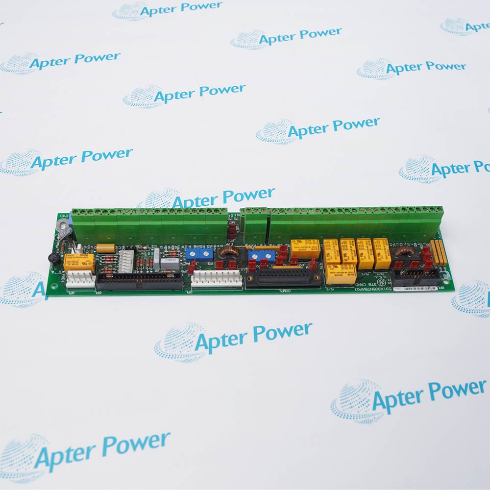
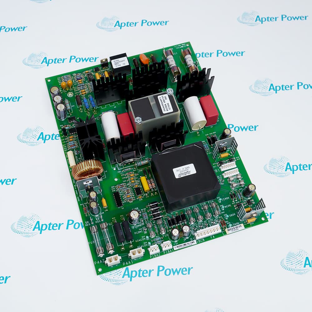
General Electric IS200JPDMG1A forms the central 28 V DC distribution point in a Mark VIe Power Distribution Module. External converters feed the board, which protects the outgoing circuits and routes power to controllers and downstream I/O distribution boards.

Separate R, S, and T buses are maintained by IS200JPDMG1A for three-supply installations. Jumper wiring can combine the buses for a single source or a redundant-source arrangement, and adjacent JPDM boards can be joined when the cabinet layout requires a wider distribution network.

From IS200JPDMG1A, fused connectors J1, J2, and J3 supply branch boards, while JCR, JCS, and JCT provide dedicated controller feeds. This separation retains the R/S/T identity from the converter inputs through the protected output paths.

A PPDA I/O pack can mount at JA1 on IS200JPDMG1A. P4 diode-ORs the three buses so feedback electronics remain powered from any available source, and P1/P2 extend the monitored PDM signal chain to other distribution boards.
Alternative Names
IS200JPDMG1A GE IS200JPDMG1A IS200-JPDM-G1A General Electric IS200JPDMG1A IS200 JPDM G1A Mark VIe JPDM G1A IS200JPDM G1A 28V Distribution Board IS2OOJPDMG1A
Technical notes
General Electric IS200JPDMG1A organizes three protected 28 VDC buses, controller feeds, branch-board outputs, and the PPDA monitoring interface.
Exceptional Service

Our Mission

  • 100% Satisfaction

    We believe expertise is priceless. With over 20 years of experience, and top engineers on staff, we can help you solve or avoid problems that threaten your business.
  • Trust Guaranteed

    Not only do we have a vast inventory, our team makes sure every piece of equipment is in working condition. Your purchases are also backed by our Warranty.
  • Expertise

    Time is money, especially when your equipment is down. We work quickly to get your equipment on its way so you can get it back up and running.

FAQS

The following is a list of questions commonly asked by our customers. Please contact us if you have a question about our process that is not answered below.
What must be traced first when one controller channel loses 28 VDC from IS200JPDMG1A?
Follow the matching R, S, or T path from IS200JPDMG1A input JR/JS/JT to its dedicated JCR/JCS/JCT controller connector and fuse.
How can IS200JPDMG1A accept one supply without leaving two buses unpowered?
The documented IS200JPDMG1A arrangement uses external jumpers to join R, S, and T when a single source feeds the board.
Why can the PPDA on IS200JPDMG1A stay active after one converter feed is lost?
IS200JPDMG1A connector P4 diode-ORs the three buses, allowing the PPDA supply to come from any bus that remains energized.
Which IS200JPDMG1A connectors belong to downstream I/O power distribution rather than controllers?
Use J1, J2, and J3 on IS200JPDMG1A for fused branch-board feeds; JCR, JCS, and JCT are reserved for controllers.
Can two IS200JPDMG1A boards participate in the same cabinet distribution arrangement?
Yes. The documented wiring permits adjacent IS200JPDMG1A boards to be connected when the required bus structure spans both assemblies.
Where should the PDM feedback ribbon continue after the PPDA position on IS200JPDMG1A?
Use the IS200JPDMG1A P1/P2 interfaces to continue monitored signals between compatible power-distribution boards and the PPDA chain.