Ask our team:
  • Phone: +86 181 0690 9650
  • E-Mail info@apterpower.com
  • Lifecycle status

    Active / Available from OEM
    Apter Power supports LR-TB5000 supply through output, response, range and IO-Link verification.

LR-TB5000

/ 4.9
1001 reviews | Need a Specific Revision?
KEYENCE LR-TB5000 is a cabled all-purpose laser sensor for 60 to 5000 mm detection with selectable discrete, analog and IO-Link functions.
In Stock
Ships by Tuesday, September 29
Fast Shipping Available
Get a quick price for LR-TB5000
Quantity
*E-mail
Company
*Mobile
*Content
Upload (gif, jpg, jpeg, png, bmp, doc, docx, xls, xlsx, ppt, pdf, csv)

Technical specifications for LR-TB5000

  • Manufacturer:
    KEYENCE
  • Part Number:
    LR-TB5000
  • Product Family:
    KEYENCE
  • Product Type:
    LR-T All-Purpose Laser Sensor
  • Stock:
    1
  • Detection Range:
    60 to 5000 mm
  • Light Source:
    Red laser, 660 nm
  • Laser Class:
    Class 2
  • Response Time:
    1, 10, 25, 100 or 1000 ms selectable
  • Discrete Output:
    NPN or PNP selectable
  • Analog Output:
    Voltage or current selectable
  • Communication:
    IO-Link 1.1
  • Supply:
    20 to 30 VDC
  • Protection:
    IP65/IP67
  • Operating Temperature:
    -20 to 55 °C
  • Weight:
    0.2 kg
  • Tariff Code:
    Please confirm the destination before shipping
  • Country of origin:
    Japan
  • Place of shipment:
    Xiamen,Fujian,China
By purchasing this item, you agree to the Terms & Conditions, ApterPower is not an authorized distributor for listed manufacturers or tradenames and therefore the manufacturer's warranty does not apply. All our products come with ApterPower's 1-year warranty.

More Information

Overview Manuals Detection Setup Output Setup Fault Checks Applications

Features:

  • Long detection span: The cabled sensor covers targets from 60 to 5000 mm after application proof.
  • Flexible outputs: Switching, analog and IO-Link options support different controller strategies.
  • Selectable response: Timing can be balanced against target speed and signal stability.
LR-TB5000 is a general-purpose laser sensor, not a personnel-protection device.

The selected output and response mode must match the controller before wiring is transferred.

Commissioning uses the actual surface, angle, distance and motion expected in production.

Apter Power can help confirm the KEYENCE LR-TB5000 LR-T All-Purpose Laser Sensor and the documented application details before quotation.
KEYENCE LR-TB5000 LR-T All-Purpose Laser Sensor Manuals,Datasheets,Link
Important Notice: Other accessories, manuals, cables, calibration data, software, etc. are not included with this equipment unless listed in the above stock item description. All prices are shown in USD.
  • Target proof: Test the least reflective or most angled production surface.
  • Range margin: Avoid commissioning at the edge of the documented distance.
  • Spot placement: Keep the laser on the intended feature throughout machine motion.
  • Mount rigidity: Prevent vibration from moving the beam off a small target.
  • Logic selection: Set NPN or PNP to match the controller input architecture.
  • Analog mode: Choose voltage or current only after confirming the receiving channel.
  • Response time: Balance fast target passage against a stable reading.
  • IO-Link record: Back up master-port and parameter data before replacement.
  • Local indication: Compare sensor status with the PLC to separate optics from wiring.
  • Background change: Recheck teach conditions after fixtures or guards move.
  • Cable strain: Inspect the fixed cable near the body when readings fail intermittently.
  • Parameter restore: Confirm downloaded IO-Link settings belong to LR-TB5000.
  • Object presence: Detects parts across extended machine clearances.
  • Position reference: Provides switching or analog feedback for controlled travel.
  • Level observation: Monitors a visible surface when material behavior is validated.
  • Connected sensing: Reports process data and parameters through an IO-Link master.
Description
Long-range object detection with a cabled laser head is the primary role of LR-TB5000. Its visible red spot gives setup personnel a direct way to align the sensing path and relate the detected surface to the required machine position.

Selectable switching, analog and IO-Link functions allow LR-TB5000 to support discrete presence, continuous feedback or parameterized sensor integration under different controller strategies, provided the chosen output is configured and verified for the intended task.

Real targets still determine the usable margin for LR-TB5000 because surface, angle, motion and background affect the optical return. Commissioning against the least favorable production condition makes the selected response mode more meaningful than the maximum catalog distance alone.
Alternative Names
LRTB5000
Technical notes
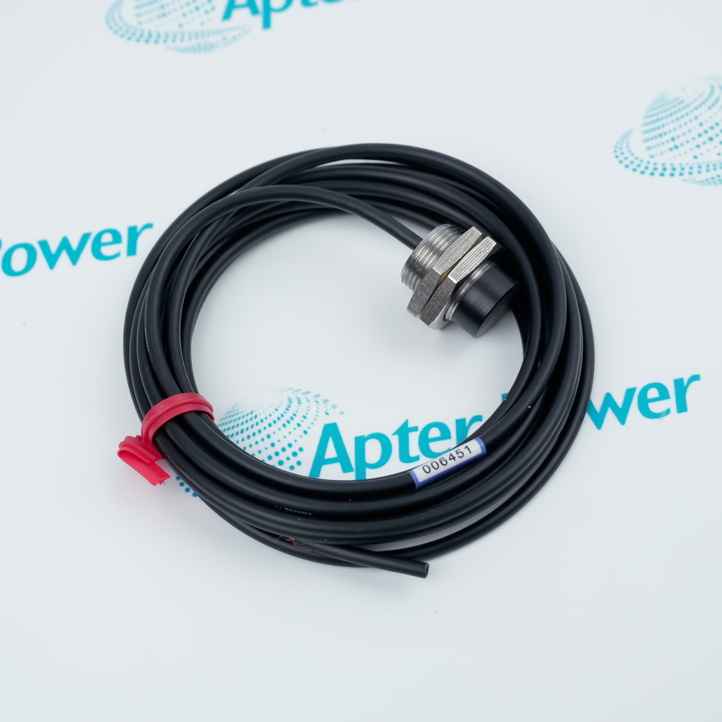
Configure LR-TB5000 output type, analog mode and response time before connecting it to the controller. Prove the least favorable target across the required distance and background, then record the accepted setting. Check laser alignment, mounting rigidity and cable strain when measurement changes, and verify IO-Link parameters after device replacement.
Exceptional Service

Our Mission

  • 100% Satisfaction

    We believe expertise is priceless. With over 20 years of experience, and top engineers on staff, we can help you solve or avoid problems that threaten your business.
  • Trust Guaranteed

    Not only do we have a vast inventory, our team makes sure every piece of equipment is in working condition. Your purchases are also backed by our Warranty.
  • Expertise

    Time is money, especially when your equipment is down. We work quickly to get your equipment on its way so you can get it back up and running.

FAQS

The following is a list of questions commonly asked by our customers. Please contact us if you have a question about our process that is not answered below.
LR-TB5000 switches correctly near the machine but becomes unstable at the far target. What should be proven?
Verify the target remains within the 60 to 5000 mm range, then check alignment, spot position, surface condition and response time.
A replacement LR-TB5000 powers up but the PLC input has the wrong logic. Which setting should be checked?
Confirm the selected NPN or PNP discrete-output mode and compare the controller input wiring with the saved machine record.
LR-TB5000 analog feedback changes scale after replacement. What should commissioning compare?
Compare voltage-versus-current selection, scaling, teach values and the receiving analog-input configuration before recalibrating the process.
Fast parts pass LR-TB5000 without a stable decision. Which control should be reviewed?
Review the selected response time against target dwell time, machine speed and the required noise margin.
An IO-Link master sees LR-TB5000 but the machine uses unexpected values. Where should diagnosis start?
Compare device parameters, process-data mapping and the controller function block with the backed-up IO-Link configuration.
An LR-TB5000 outage spare is being issued. Which configuration details must travel with it?
Use the exact model, cable arrangement, output selections, taught range, response time and IO-Link parameter record.

Product Browsing History