

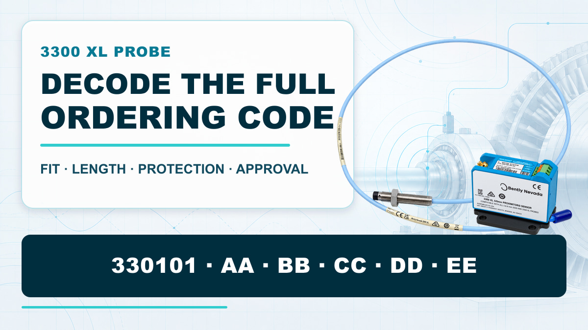
During a turbine or compressor outage, a maintenance team may need one replacement proximity probe before the machine can return to service. The request often begins with a short description: “Bently Nevada 3300 XL, 8 mm probe, one-metre cable.” That sounds specific, but it is not enough to identify the correct product.
A visually similar probe may have the wrong mounting thread. A cable may be mechanically connectable but produce the wrong total electrical length. An armored probe may be supplied where the installation requires an unarmored lead, or an approval suffix may not match the site documentation. Each of these differences is contained in the ordering code.
This is why understanding the full code matters. It is not only a task for instrumentation engineers. Maintenance planners need it to avoid extending an outage, buyers need it to compare quotations correctly, and suppliers need it to identify the exact configuration rather than quote a similar-looking product.
Is the Ordering Code Really Important?
Yes. For a Bently Nevada 3300 XL 8 mm probe, the ordering code answers five practical questions:
- Will the probe fit the existing threaded hole or mounting bracket?
- Is the probe body long enough to reach the target at the correct installation depth?
- Will the probe and extension cable match the electrical length of the Proximitor Sensor?
- Does the cable have the required mechanical and environmental protection?
- Does the ordered configuration carry the approval option required by the project?
The probe tip diameter alone cannot answer any of these questions. Even when two products are both described as “3300 XL 8 mm probes,” their complete codes may describe different mounting, cable and approval configurations.
Start with the Measurement Chain, Not the Probe Alone
A standard 3300 XL 8 mm proximity transducer system contains:
- A proximity probe.
- An extension cable, except in a one-metre probe-only system.
- A Proximitor Sensor.
The probe observes a conductive target without contact. The Proximitor Sensor converts the change in probe-to-target distance into a proportional voltage used for static position and dynamic vibration measurement. Common duties include radial shaft vibration, axial position, Keyphasor phase reference and speed measurement on fluid-film bearing machines.
The three components form one calibrated measurement chain. Selecting the probe correctly is essential, but it is only the first part of the job.
The 3300 XL Probe Code in One View
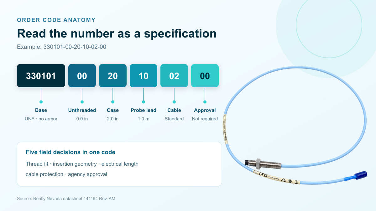
The standard forward-mount threaded probe uses this format:
Part Number – AA – BB – CC – DD – EE
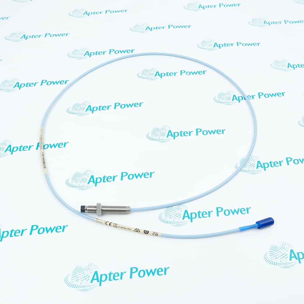
Consider the photographed model 330101-00-20-10-02-00:
| Code position | Value | What the value tells the buyer |
|---|---|---|
| Part number | 330101 | 3/8-24 UNF forward-mount probe without armor |
| AA | 00 | 0.0 in unthreaded length |
| BB | 20 | 2.0 in overall case length |
| CC | 10 | 1.0 m total probe length |
| DD | 02 | Standard cable with ClickLoc connector; factory-installed connector protector not selected |
| EE | 00 | Agency approval not required |
Instead of treating the number as one long string, read it as a short technical specification. The following application scenarios show why each section matters.
Scenario 1: Replacing a Probe in an Existing Bearing Housing
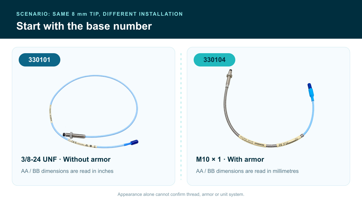
Suppose a maintenance engineer removes a damaged probe from a compressor bearing housing. The replacement has the correct 8 mm tip, but its thread is M10 × 1 while the installed bracket is 3/8-24 UNF. The probe cannot be treated as equivalent simply because the outside diameters appear close.
The six-digit base number identifies the thread system and whether the standard probe lead has armor:
| Base number | Mounting thread | Cable armor | AA and BB unit system |
|---|---|---|---|
| 330101 | 3/8-24 UNF | Without armor | Inches |
| 330102 | 3/8-24 UNF | With armor | Inches |
| 330103 | M10 × 1 | Without armor | Millimetres |
| 330104 | M10 × 1 | With armor | Millimetres |
This table gives the first selection decision:
- Choose 330101 or 330102 for a 3/8-24 UNF installation.
- Choose 330103 or 330104 for an M10 × 1 installation.
- Choose the armored version when the lead requires additional mechanical protection.
Armor protects the cable against physical damage. It is not the same as a connector protector, FluidLoc cable or an underwater probe construction. Those features solve different problems and should not be used as interchangeable descriptions.
Scenario 2: The Thread Is Correct, but the Probe Cannot Reach the Target
A probe may have the correct thread and still be unsuitable for the machine. The unthreaded length and overall case length determine how the probe passes through a housing, bracket or standoff and whether sufficient thread remains for secure adjustment.
For 330101 and 330102 imperial probes:
| Code | Meaning | Ordering range | Example |
|---|---|---|---|
| AA | Unthreaded length | 0.0 to 8.8 in, in 0.1 in increments | 30 = 3.0 in |
| BB | Overall case length | 0.8 to 9.6 in, in 0.1 in increments | 60 = 6.0 in |
The unthreaded length must be at least 0.8 in shorter than the overall case length.
For 330103 and 330104 metric probes:
| Code | Meaning | Ordering range | Example |
|---|---|---|---|
| AA | Unthreaded length | 0 to 230 mm, in 10 mm increments | 06 = 60 mm |
| BB | Overall case length | 20 to 250 mm, in 10 mm increments | 13 = 130 mm |
The unthreaded length must be at least 20 mm shorter than the overall case length.
The unit change is easy to miss. In 330104-00-06-05-01-05, BB = 06 means a 60 mm case. It does not mean 0.6 in or 6 mm. Reading the base number before AA and BB prevents this common mistake.
Scenario 3: The Probe Fits, but the Measurement Chain Is the Wrong Length
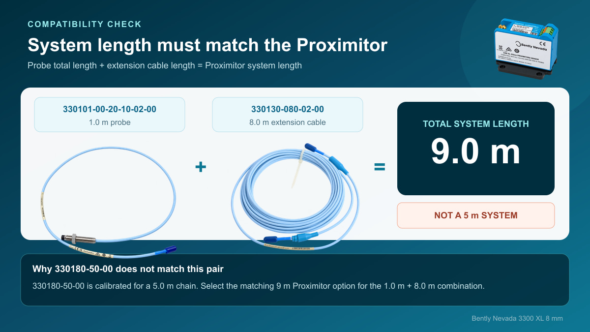
This is one of the most important compatibility checks in the entire 3300 XL system.
Decode the CC Code and Build the System Length
The CC group identifies the total probe length, including its integral lead. Use it with the extension-cable length to build the Proximitor Sensor system length.
| CC code | Total probe length |
|---|---|
| 05 | 0.5 m |
| 10 | 1.0 m |
| 15 | 1.5 m |
| 20 | 2.0 m |
| 30 | 3.0 m; available only on 330101 and intended for a 9 m system |
| 50 | 5.0 m; intended for a 5 m Proximitor Sensor |
| 90 | 9.0 m |
Check the Photographed Parts
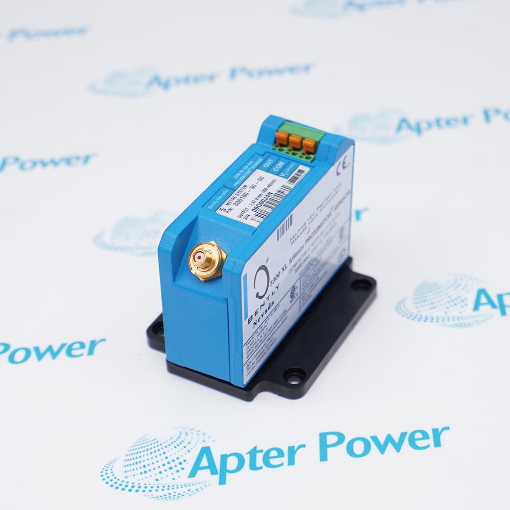
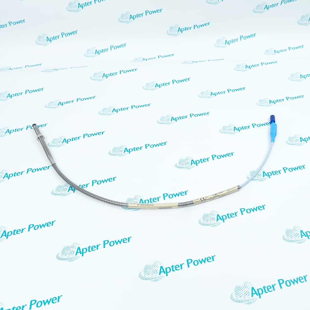
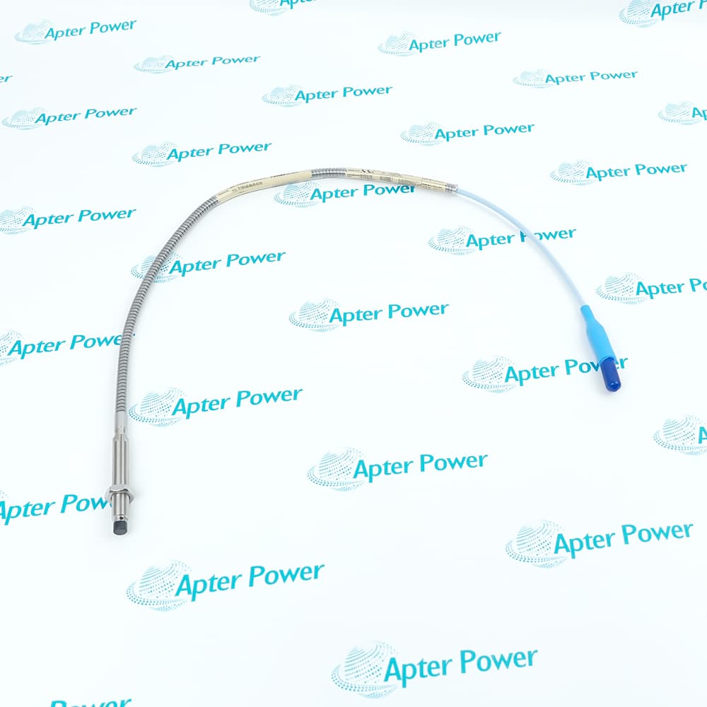
The four real products illustrate why matching the family and total electrical length matters.
Likewise, the 0.5 m 330104-00-06-05-01-05 plus the 8.0 m cable totals 8.5 m, which does not match a standard 1 m, 5 m or 9 m Proximitor system. A compatible 9 m chain would require an 8.5 m extension cable with this probe.
This is exactly why three products that share the same platform and connectors should not automatically be photographed, quoted or installed as one compatible set.
Scenario 4: Selecting Cable Protection for the Machine Environment
After the mechanical and electrical-length decisions are correct, the DD group defines connector protection and cable construction for standard probes:
| DD code | Factory-installed connector protector | Cable construction |
|---|---|---|
| 01 | Included | Standard cable |
| 02 | Not selected | Standard cable |
| 11 | Included | FluidLoc cable |
| 12 | Not selected | FluidLoc cable |
These options address different installation risks:
- Armor, selected through the probe base number, protects the lead against mechanical damage.
- A connector protector improves environmental protection around the ClickLoc connection.
- FluidLoc is intended to reduce oil or other liquid migration through the cable interior.
- Underwater service requires a separate underwater probe design.
For connections exposed to turbine oil, the Bently Nevada datasheet advises against using silicone tape as a substitute for the connector-protection arrangement. The cable option should therefore be selected from the actual installation environment, not simply from price or appearance.
Scenario 5: The Plant Requires Hazardous-Area Documentation
The EE group identifies the agency approval option in the standard ordering table:
| EE code | Meaning |
|---|---|
| 00 | Agency approval not required |
| 05 | CSA, ATEX and IECEx approvals |
Code 05 does not by itself approve every installation. The final design still depends on the exact system components, barriers, wiring, installation drawing and site area classification. When an existing label carries a regional or document-controlled suffix such as CN, BR or RU, do not automatically replace that suffix with 05. The exact certificate and current ordering documentation should be reviewed before quotation or installation.
What About Reverse-Mount, Smooth-Case and High-Temperature Probes?
The five-suffix format described above applies to the common forward-mount 330101, 330102, 330103 and 330104 probes. Other constructions use different base numbers:
| Construction | Standard-temperature base numbers | Extended-temperature base numbers | When it is considered |
|---|---|---|---|
| Forward mount, 3/8-24 UNF | 330101 / 330102 | 330191 / 330192 | Common imperial threaded mounting |
| Forward mount, M10 × 1 | 330103 / 330104 | 330193 / 330194 | Common metric threaded mounting |
| Reverse mount | 330105 / 330106 | 330195 / 330196 | Rear-access or sleeve-based mounting |
| Smooth case | 330140 / 330141 | 330197 / 330198 | Clamp-bracket installation rather than a threaded case |
The extended-temperature-range probe is rated up to 218 °C, and the ETR extension cable is rated up to 260 °C. ETR components can be used with the standard 3300 XL Proximitor Sensor, but when an ETR component is included, the system is subject to the ETR accuracy limits. This is a permitted system configuration, not a reason to assume that the standard-temperature accuracy specification remains unchanged.
Compatibility: What Can Be Mixed and What Must Stay Matched?
Within the 3300 XL 8 mm family, probes, extension cables and Proximitor Sensors are designed to be interchangeable when the correct family, calibration and total electrical length are maintained. Individual standard components do not require bench matching for the standard AISI 4140 steel calibration.
The 3300 XL 8 mm family is also electrically and physically interchangeable with earlier non-XL 3300-series 5 mm and 8 mm components, subject to the published installation conditions. When XL and non-XL components are mixed, system performance is limited to the older non-XL specification. Mechanical connection therefore does not mean that every XL performance claim is retained.
Standard systems are calibrated to an AISI 4140 steel target. Other target-material calibrations are available, but the published standard accuracy and interchangeability specifications do not apply in the same way to those systems. If the shaft, collar or observed target is not AISI 4140 steel, include the target material and existing calibration information in the RFQ.
Different proximity-probe families must remain correctly matched. An 8 mm probe should not be connected to an NSv, 11 mm, 25 mm or 50 mm Proximitor Sensor merely because a connector appears similar. Bently Nevada also advises against combining probes, extension cables and drivers from different manufacturers. A mixed system may change scale factor or linearity and can affect the effective alarm or trip response.
Which Bently Nevada Probe Family Should Be Considered?
| Probe family | Nominal linear range | Nominal scale factor | Typical selection reason |
|---|---|---|---|
| 3300 5 mm | 2.0 mm | 7.87 V/mm | The 8 mm body is physically too large for the available mounting space |
| 3300 XL 8 mm | 2.0 mm | 7.87 V/mm | Normal starting point for shaft vibration, position, Keyphasor and speed measurement where the probe fits |
| 3300 XL NSv | 1.5 mm | 7.87 V/mm | Side-view, rear-view, counterbore or small-target clearance restricts a standard 5/8 mm system |
| 3300 XL 11 mm | 4.0 mm | 3.94 V/mm | A longer measurement range is required |
| 3300 XL 25 mm | 12.7 mm | 0.787 V/mm | Differential-expansion measurement on medium to large steam turbine generators |
The 8 mm probe is recommended where its dimensions fit because its larger probe body and thicker tip encapsulation provide greater resistance to physical abuse than the smaller 5 mm construction. That does not make the 8 mm family a universal substitute: mounting space, measurement range, side-view clearance and the matching Proximitor family still govern the decision.
How to Read an Actual Nameplate
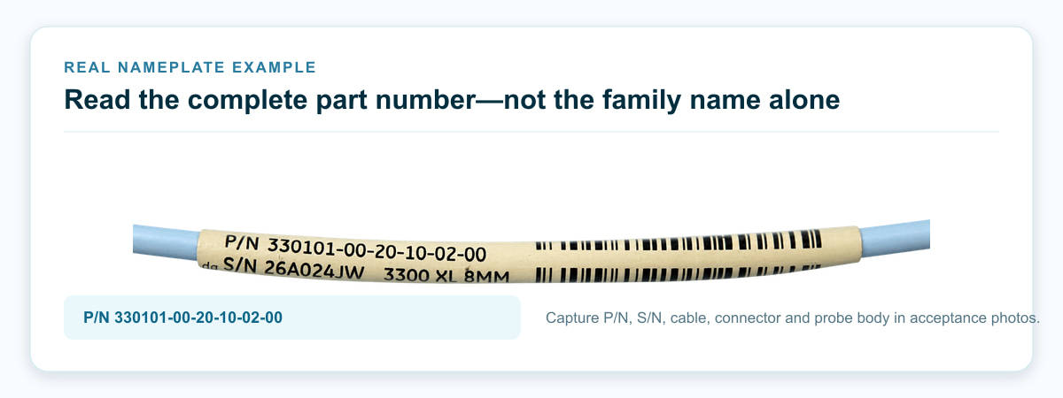
The photographed label for 330101-00-20-10-02-00 provides a complete example:
- 330101: forward-mount 8 mm probe, 3/8-24 UNF, without armor.
- 00: 0.0 in unthreaded length.
- 20: 2.0 in overall case length.
- 10: 1.0 m total probe length.
- 02: standard cable and ClickLoc connector, without the selected factory-installed connector protector.
- 00: agency approval not required.
A useful acceptance photograph should show more than the code alone. Include the complete part number, manufacturer marking, serial number or date code where present, probe tip, thread, armor or unarmored lead and ClickLoc connector. A close-up label confirms identity, while an overall photograph confirms the visible mechanical configuration and product condition.
Six Ordering Mistakes That Cause Avoidable Delays
- Ordering by “8 mm probe” without checking the complete part number.
- Reading AA and BB as inches on a metric base number, or as millimetres on an imperial base number.
- Treating CC as a convenient routing length rather than part of the calibrated system length.
- Confusing armor, connector protection, FluidLoc and underwater construction.
- Treating an approval suffix as approval of the entire hazardous-area installation.
- Combining different electrical lengths, probe families or manufacturers because the connectors fit.
What to Send with a Bently Nevada 3300 XL RFQ
An accurate quotation should begin with:
- The complete probe part number from the label.
- The extension-cable part number and length.
- The Proximitor Sensor part number and mounting option.
- The shaft or target material and any special calibration information.
- The required hazardous-area or country approval.
- Quantity, destination and clear photographs of the labels, probe body, cable and connectors.
Official Technical Sources
- Bently Nevada, 3300 XL 8 mm Proximity Transducer System Datasheet, 141194 Rev. AM: https://dam.bakerhughes.com/m/23d2a1de24360b13/original/3300-XL-8mm-Proximity-Transducer-System-Datasheet-141194-pdf.pdf
- Bently Nevada, Proximity Probes, Sensors & Transducer Systems: https://www.bakerhughes.com/bently-nevada/sensors/proximity-sensors
- Bently Nevada, Proximity Probe System Interchangeability—Don’t Build a “Frankenstein” System: https://www.bakerhughes.com/bently-nevada/orbit-home/orbit-article/proximity-probe-system-interchangeability-dont-build
- Bently Nevada, 3300 5 mm Transducer System Datasheet, 172036: https://dam.bakerhughes.com/m/3048672186f80f8/original/3300-5-mm-Transducer-System-Datasheet-172036-pdf.pdf
- Bently Nevada, 3300 XL NSv Proximity Transducer System Datasheet, 147385 Rev. R: https://dam.bakerhughes.com/m/7a79b853504f738/original/3300-XL-NSv-Proximity-Transducer-System-Datasheet-147385-pdf.pdf
- Bently Nevada, 3300 XL 11 mm Proximity Transducer System Datasheet, 146256 Rev. T: https://dam.bakerhughes.com/m/27a2d91f28aadd41/original/3300-XL-11mm-Proximity-Transducer-System-Datasheet-146256-pdf.pdf
- Bently Nevada, 3300 XL 25 mm Proximity Transducer System Datasheet, 163236 Rev. M: https://dam.bakerhughes.com/m/69ee6d965e942dae/original/3300-XL-25mm-Proximity-Transducer-System-Datasheet-163236-pdf.pdf
Ordering tables and approvals can change with document revisions. Check the current Baker Hughes/Bently Nevada publication and the exact certificate set before releasing a purchase order.





Leave Your Comment