Features:
- A built-in oscillator generates motion commands for two-phase stepping motors.
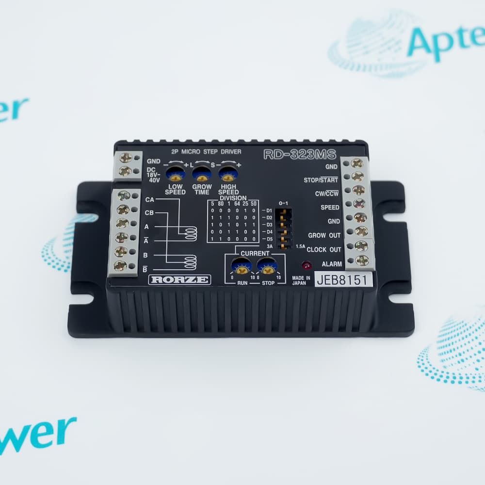
- Analog voltage at the SPEED terminal varies the commanded stepping rate.
- Current-down and fault-detection circuits support controlled driver operation.
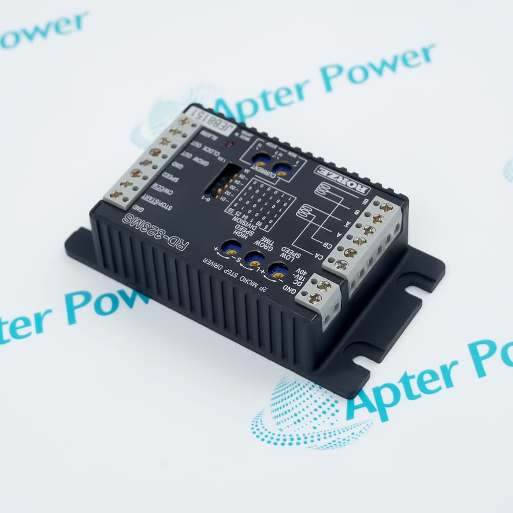
RD-323MS uses a unipolar constant-current chopper stage to regulate winding current throughout each microstep.
Its selectable division table provides up to eighty command pulses for one basic motor step.
Low-speed, high-speed, and acceleration controls shape the motion profile directly at the driver.
The RORZE RD-323MS 2-Phase Microstepping Motor Driver may still be available for purchase and support from Apter Power beyond End-Of-Life (EOL) by the manufacturer (OEM).
RORZE RD-323MS 2-Phase Microstepping Motor Driver Manuals,Datasheets,Link
Important Notice: Other accessories, manuals, cables, calibration data, software, etc. are not included with this equipment unless listed in the above stock item description. All prices are shown in USD.
Winding and Current Requirements
- Motor construction: Compatible loads are two-phase HB or PM stepping motors.
- Lead arrangement: The unipolar output is intended for four- or six-lead winding connections.
- Phase setting: Driver current is adjustable from 0.3 to 3 A for each motor phase.
- Voltage boundary: Motor rated voltage must remain within the documented relationship to the DC supply.
Oscillator and Ramp Control
- Clock source: The internal oscillator reaches a maximum stepping frequency of 700 kpps.
- Division range: Selectable clock output spans one to eighty pulses for each basic step.
- Speed input: Voltage at the SPEED terminal continuously adjusts the oscillation rate.
- Ramp timing: Acceleration and deceleration are adjustable from 20 milliseconds to 3 seconds.
Driver Safeguards
- Thermal detection: An internal circuit reacts when the driver exceeds its allowable temperature.
- Current monitoring: Overcurrent protection limits damage from an abnormal output condition.
- Supply supervision: Low-voltage detection identifies an inadequate 18-to-40 VDC input.
- Stopped-motor reduction: Automatic current down lowers phase current after roughly 0.3 seconds of inactivity.
Mounting and Cooling
- Supply connection: The DC input must remain between 18 and 40 V including ripple.
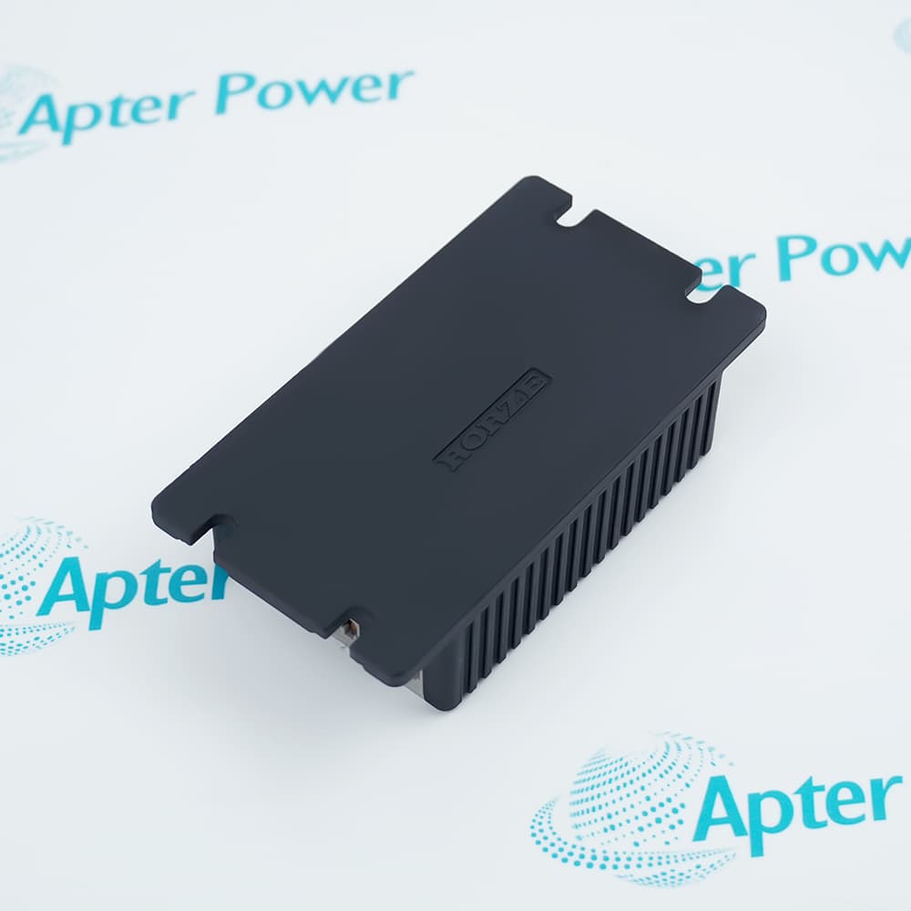
- Case cooling: The enclosure should conduct heat to a suitable metal mounting surface.
- Temperature check: Operating airflow must keep the case at or below the stated 60°C limit.
- Forced ventilation: A fan is added when natural heat dissipation cannot maintain the required case temperature.